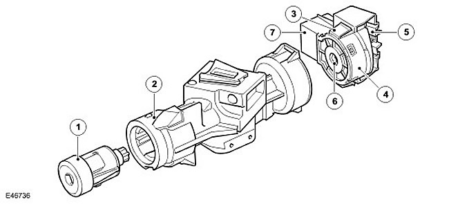
| Item name | Spare part catalog number | Description |
| 1 | - | Lock cylinder |
| 2 | - | Steering column lock |
| 3 | - | Locking tongue |
| 4 | - | Ignition switch |
| 5 | - | Wiring harness connector |
| 6 | - | Drive shaft mounting |
| 7 | - | Key lock solenoid |
The ignition switch is located on the left side of the steering column lock assembly. The ignition switch is secured to the cast housing of the steering column lock by two locking tabs that fit into corresponding grooves in the housing.
The lock has a groove for the drive shaft, which passes through the steering column lock. This shaft rotates when the ignition key is turned in the ignition lock cylinder. The rotation is transmitted to the drum in the ignition lock, which moves two electrical contacts to select the desired ignition position. In each of the three positions of the ignition lock, a spring-loaded ball enters a socket. Due to this, the driver feels when the desired position of the key in the lock has been reached.
On vehicles with an automatic transmission, an electromagnet is installed in the ignition switch. The electromagnet, whose operation is controlled by the transfer case control module via one wire, prevents the key from being removed from the lock unless the gear selector lever is in the PARK (P) position. The transfer case receives information about the transmission mode via the CAN bus from the transmission control module.
When current flows through the electromagnet, it extends a pin that prevents the ignition key from being turned all the way to the '0' (off) position. This prevents the key from being removed until the gear selector is in the PARK position.
Comments on this article