Torque specification
| Description | Nm | lb-ft |
| Steering Column Switch Torx Head Screws | 1,5 | 1,0 |
Location of elements
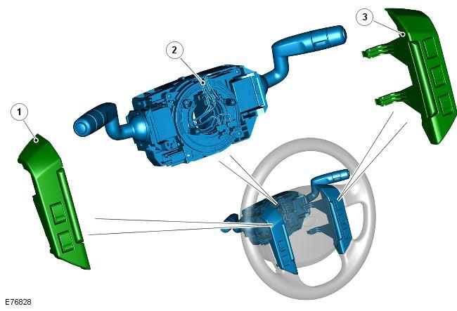
| Pos. | spare part no | Name |
| 1 | - | Cruise Control Switches |
| 2 | - | Steering column cover with multifunction switches and movable contact group |
| 3 | - | Audio Control Switches |
The windshield wiper control switch is located on the right side of the case and is secured with two screws. The switch is connected to the main wiring harness using a connector on the back of the switch. The lever performs the following functions:
- Intermittent wiper, constant low speed and constant high speed
- Enabling one-time windshield cleaning
- Switching on the windshield wiper and washer
- Switching on the rear window wiper and washer
- Selecting the duration of the cycle in intermittent operation of the cleaner
The turn signal switch is located on the left side of the housing and is secured with 2 screws. The switch is connected to the main wiring harness using a connector on the back of the switch. The lever performs the following functions:
- Switching on the left / right turn signal
- Switching low / high beam headlights
- High beam signaling
- Trip computer function selection (in the presence of)
The control button allows the driver to sequentially select menu options and reset the odometer. Trip computer information is displayed in the message center on the instrument cluster (only in high level instrument clusters).
Steering wheel mounted switches on the right side of the driver's airbag control the audio unit and telephone. The switches located to the left of the driver's airbag control the cruise control system.
The clock spring is located in front of the case and is secured with four screws. The clock spring fits into grooves in the steering wheel hub and rotates with it. The clock spring has a protrusion that turns off the direction indicators when the steering wheel is returned to its original position. For more information, see chapter: Airbag and Pretensioner Restraint System (SRS) (501-20B Secondary Restraint System Description and Operation).
Comments on this article