car logo Ford
car logo Volkswagen
car logo BMW
car logo Opel
car logo Audi
car logo Toyota
car logo Peugeot
English Русский
Български
Беларускі
Український
Српски
Hrvatski
Română
Polski
Slovenský
Magyar


Main
Freelander
Discovery
Range Rover
Defender
Contacts
Articles

Transfer case rear output shaft seal (Defender 2007+)

 
  • Main
  • Defender
  • Defender 2007+
  • Power unit
  • Transfer case
  • Transfer case rear output shaft seal
 
        0  
Contents: Removal ⇩ Installation ⇩

Removal


1. Loosen the brake shoe adjusting bolt.
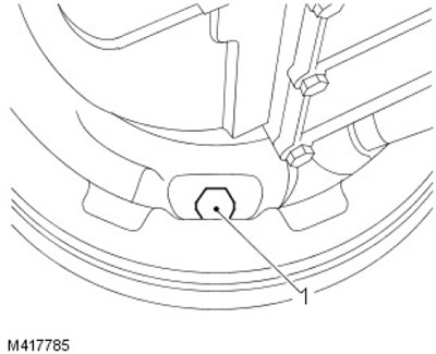
1. Loosen the brake shoe adjusting bolt.


2. Remove the rear propeller shaft.

For more information, refer to the chapter: Rear Propeller Shaft (205-01 Cardan shaft, Removal and installation).

3. Remove the brake drum mounting screw.

4. Remove the brake drum.

5. Secure the transfer case drive flange using LRT-51-003, loosen and discard the drive flange nut, remove and discard the steel and felt washers.
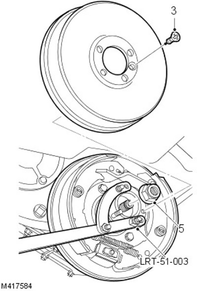
5. Secure the transfer case drive flange using LRT-51-003, loosen and discard the drive flange nut,…


6. Using LRT-99-500 if necessary, remove the drive flange from the transfer case.
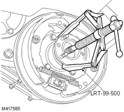
6. Using LRT-99-500 if necessary, remove the drive flange from the transfer case.


7. Remove the secondary shaft rear oil seal from the transfer case and discard it.
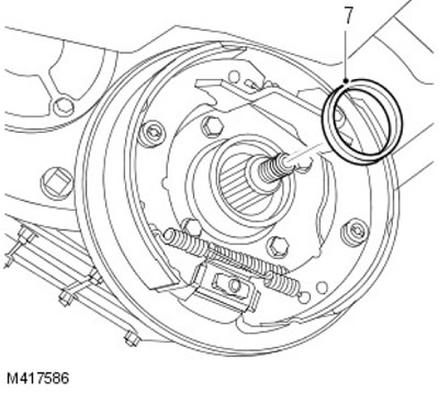


7. Remove the secondary shaft rear oil seal from the transfer case and discard it.


Installation


1. Clean the drive flange splines, bearing mating surfaces and gaskets to remove oil and debris. Use Loctite 7063 Degreaser Cleaner.

2. Clean the seal recess, output shaft splines, threads and mating surfaces to remove oil and debris. Use Loctite 7063 Degreaser Cleaner.

3.
CAUTION: The seal must be installed dry.


NOTE: Use the end of the tool marked 'REAR' to install the seal.


Install new seal using LRT-41-012.
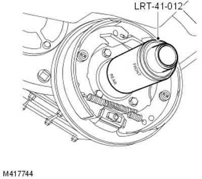
Install new seal using LRT-41-012.


4.
CAUTION: Remove Loctite 648 from bearing when installing drive flange. Failure to do so may result in vehicle damage.


Holding the drive flange by the protruding end, apply Loctite 648 to the splines as shown.
  • 1. Apply a continuous strip along the splines.
  • 2. Apply a second continuous bead 5mm from the end of the flange.

The original text can be found at: LRman.ru
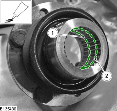


2. Apply a second continuous bead 5mm from the end of the flange.


5.
NOTE: It is not necessary to install a new felt filter.


NOTE: Remove excess Loctite 648 from drive flange before installing steel washer.


Install the drive flange onto the output shaft, making sure the drive flange is fully seated. Install a new steel washer

6.
CAUTION: Do not use power or air tools to tighten the drive flange nut.


Install LRT-51-003, screw on new drive flange nut and tighten to 165 Nm (122 lbf/ft).
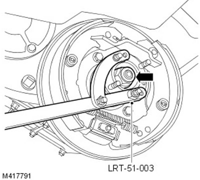
Install LRT-51-003, screw on new drive flange nut and tighten to 165 Nm (122 lbf/ft).


7. Install the brake drum and tighten the screw.

8. Tighten the adjuster bolt to 25 Nm, then back it out 1/2 turn.

9. Make sure the brake drum can rotate freely.

10. Install the driveshaft.

For more information, refer to the chapter: Rear Propeller Shaft (205-01 Cardan shaft, Removal and installation).


11. Add oil to the transfer case.

For more information, refer to the chapter: Draining and Filling Transfer Case Transmission Fluid (308-07A Transfer Case - ID4 2.4L Diesel Engine, General Procedures).


This article is available at russian, bulgarian, belarusian, ukrainian, serbian, croatian, romanian, polish, slovak, hungarian
Article review: Saveliy Ushakov


Previous articles
Transfer case specifications
Description and operating principle of the transfer case
Draining and filling the transfer case transmission fluid
Adjusting the Transfer Case High/Low Range Selector Rod
Removal the transfer case
Installing a transfer case
Transfer case rear cover — removal and installation
Transfer case lower cover — removal and installation

Current article
Transfer case rear output shaft seal

Next articles
Transfer case primary shaft seal
Transfer case front output shaft seal
Adjusting the differential lock switch
Downshift alarm switch
Differential lock switch


Similar articles from Land Rover repair manuals:
• Transfer case rear oil seal Freelander 2 (2006-2014)
• Transfer case drive shaft seal Freelander 1 (1997-2006)
• Transfer Case Rear Output Shaft Seal 2.7L Discovery 3 (2004-2009)
• Disassembling the transfer case components Discovery 1 (1989-1998)
• Rear output shaft seal Range Rover 3 (2001-2012)

Comments on this article


No comments yet


How much will 42 + 31 =


Defender 2007+ 
  • General information
  • Maintenance
  • Identification codes
  • Power unit
  • Diesel engine ID4 2.4L
  • Engine inspection
  • Engine cooling
  • Fuel supply
  • Fuel tank
  • Exhaust system
  • Accessory drive
  • Air filtration
  • Electronic parts
  • Mechanical gearbox
  • Transfer case
  • Clutch
  • Chassis
  • Car suspension
  • Wheels and tires
  • Steering
  • Steering column
  • Brake system
  • Front drive axle
  • Rear drive axle
  • Cardan shaft
  • Body and coating
  • Interior trim
  • Instrument panel and console
  • Exterior finish
  • Lockable body parts
  • Handles, locks, latches
  • Glass, frames and mechanisms
  • Windshield wipers and washers
  • Seats
  • Electrical equipment
  • Battery
  • Generator and regulator
  • Lighting and headlights
  • Winch
  • Heating and ventilation
  • Instrument panel
  • Other electronics


LRman.ru © 2013-2026 | Mobile version | Free Lander | Discovery | Range Rover | Defender | Contacts | | Sitemap |
Car repair and service instructions Land Rover: Freelander, Discovery, Range Rover, Defender
We use cookies to make pages load faster and provide a more user-friendly experience 🍪