


Contents: Arrangement of elements ⇩ Transfer case cross section ⇩ Review ⇩ Main crankcase ⇩ Secondary shaft drive gear ⇩ Intermediate gears ⇩ Interaxle differential assembly ⇩ Front axle drive shaft housing ⇩ Housing and selector assembly ⇩ Fork and shaft of the differential…⇩ Rear axle drive shaft housing ⇩ Lubrication ⇩ Job ⇩
Arrangement of elements
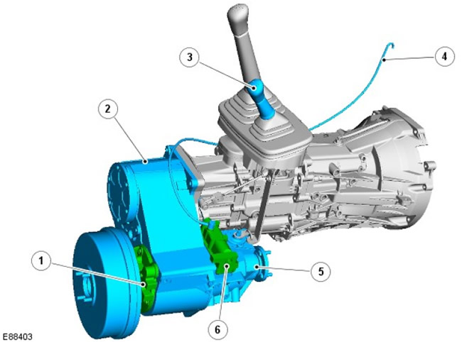
| Pos. | Spare part number | Name |
| 1 | - | Rear axle drive shaft housing |
| 2 | - | Main crankcase |
| 3 | - | Transfer case selector lever |
| 4 | - | Ventilation duct |
| 5 | - | Front axle drive shaft housing |
| 6 | - | Selector housing |
Transfer case cross section
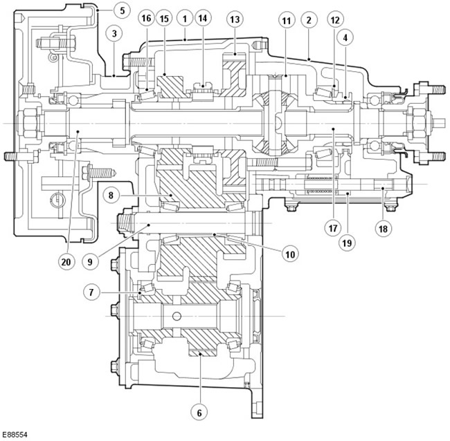
| Pos. | Spare part number | Name |
| 1 | - | Main crankcase |
| 2 | - | Front axle drive shaft housing |
| 3 | - | Rear axle drive shaft housing |
| 4 | - | Cam clutch |
| 5 | - | Transmission brake |
| 6 | - | Secondary shaft drive gear |
| 7 | - | Selective adjusting shim for setting the preload of the pinion bearing |
| 8 | - | Intermediate gear block |
| 9 | - | Intermediate shaft |
| 10 | - | Spacer |
| 11 | - | Differential assembly |
| 12 | - | Selective differential bearing preload adjusting shim |
| 13 | - | Low range gear |
| 14 | - | High/Low Range Selector Bushing and Hub |
| 15 | - | High Range Gear and Bushing |
| 16 | - | Rear differential bearing |
| 17 | - | Front axle drive shaft |
| 18 | - | Differential lock selector shaft |
| 19 | - | Selector fork |
| 20 | - | Rear axle drive shaft |
Review
The transfer case serves the operation of the permanent all-wheel drive, provides a two-stage gear reduction, combines the outputs of the high and low ranges with a mechanically locked central differential ("diff-lock" mode). The high range is characterized by a gear ratio of 1.211:1 and the low range is 3.269:1.
Selection of high or low range, as well as diff-lock mode, is accomplished using a single lever located near the main gearshift lever.
The transfer case is mounted at the rear of the main gearbox and transmits power to the front and rear axle differentials via cardan shafts.
The differential unit is integrated with the drive shafts, which compensates for the difference in speed between the front and rear drive shafts. To improve traction and prevent all power from being transferred to the differential of the drive axle in order to add even the slightest traction, a "diff-lock" mode is provided. The "diff-lock" mode should only be engaged in severe off-road conditions when traction is low. It should be disengaged as soon as possible, for example when it becomes possible to develop a sufficiently high traction force. Engaging the differential lock initiates mechanical engagement of the cam clutch on the front drive shaft, which locks the center differential and provides a fixed drive, thanks to which the front and rear drive shafts are transferred the same power.
The transfer case contains 3 main units:
- Main crankcase
- Front axle drive shaft housing
- Rear axle drive shaft housing
All housings and covers are sealed on the main crankcase with a sealant. The rotary seals of the outlet flange are protected from dirt and water by special reflectors.
Main crankcase
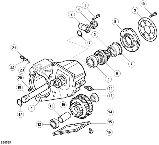
| Pos. | Spare part number | Name |
| 1 | - | Main crankcase |
| 2 | - | Lock washer |
| 3 | - | Lock plate bolt |
| 4 | - | Screw (with punching locking) intermediate shaft |
| 5 | - | Bearings and outer bearing rings of the secondary shaft drive gear |
| 6 | - | Secondary shaft drive gear |
| 7 | - | Selective adjustment shim |
| 8 | - | Secondary shaft drive gear bearing housing |
| 9 | - | Cover/Power take-off box cover |
| 10 | - | Cap bolt |
| 11 | - | Oil temperature switch (if it is installed) |
| 12 | - | Bearings and outer bearing rings of intermediate gears |
| 13 | - | Crumple spacer |
| 14 | - | Intermediate gears |
| 15 | - | Bottom cover |
| 16 | - | Bottom cover bolt |
| 17 | - | Intermediate shaft sealing rings |
| 18 | - | Intermediate shaft |
| 19 | - | Secondary shaft oil seal |
| 20 | - | Dowel pin |
| 21 | - | High/Low Range Selector Locking Plug |
| 22 | - | High/Low Range Selector Locking Spring |
| 23 | - | High/Low Range Selector Locking Ball |
The main crankcase carries:
- secondary shaft drive gear
- intermediate gears
- interaxle differential assembly
The front and rear axle drive shaft housings are bolted to each side of the main crankcase.
Secondary shaft drive gear
The secondary shaft of the gearbox has a splined connection with the secondary shaft pinion, which is supported by tapered roller bearings.
The preload of the pinion bearing is provided by means of a selective adjustment lining located in the bearing housing.
Intermediate gears
The intermediate gear block is supported by tapered roller bearings located at each end of the block and seated on an intermediate shaft, which in turn is supported at the front and rear by the main housing.
The intermediate gear bearing preload is provided by a deformable spacer element located between the bearings. The compression force applied to the spacer element is created by a nut located at the end of the intermediate shaft.
To install the bearings, the diameter of the intermediate gear hole on each side is machined with a step.
Interaxle differential assembly
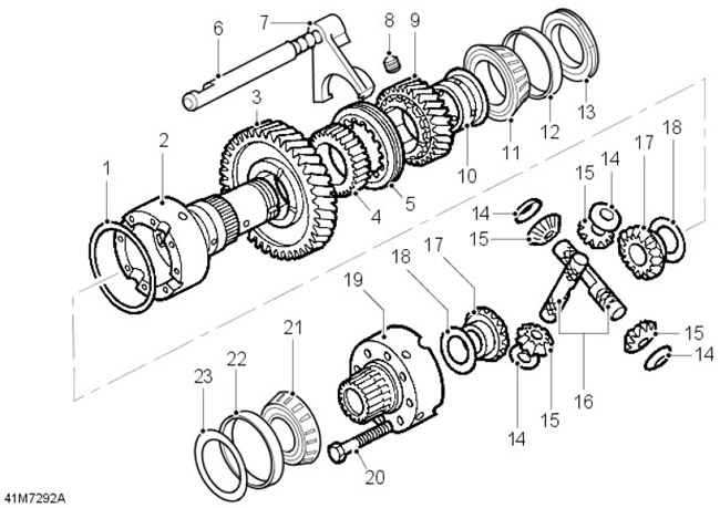
| Pos. | Spare part number | Name |
| 1 | - | Retaining ring |
| 2 | - | Differential Cup - Rear Section |
| 3 | - | Low range gear |
| 4 | - | High/Low Range Hub |
| 5 | - | High/Low Range Selector Sleeve |
| 6 | - | High/Low Range Selector Shaft |
| 7 | - | High/Low Range Selector Fork |
| 8 | - | High/Low Range Selector Fork Set Screw |
| 9 | - | High range gear |
| 10 | - | High Range Gear Bushing |
| 11 | - | Rear differential bearing |
| 12 | - | Outer bearing ring |
| 13 | - | Bearing fastening nut |
| 14 | - | Plate Thrust Washers |
| 15 | - | Planetary gears of differential |
| 16 | - | Axles |
| 17 | - | Bevel gears of semi-axles |
| 18 | - | Selective thrust washers |
| 19 | - | Differential Cup - Front Section |
| 20 | - | Differential cup bolt |
| 21 | - | Front differential bearing |
| 22 | - | Outer bearing ring |
| 23 | - | Selective adjustment shim |
The center differential assembly is supported by tapered roller bearings at the front and rear; the outer race of the front bearing is located in the front axle drive shaft housing, and the outer race of the rear bearing is located in the main crankcase near the rear axle drive shaft housing. Bearing preload is provided by means of a selectively selected adjusting shim located in the front axle drive shaft housing.
The rear shaft of the center differential contains the low range gear, the high/low range selector sleeve and hub, the high range gear and sleeve, and the rear differential bearing. These elements are secured to the shaft with a special nut.
The differential assembly comprises front and rear cup sections with integral axles connected to the bevel gears of the half-shafts and satellites mounted on the axles in the cup sections. Non-selectively matched plate thrust washers control the engagement of the satellites with the bevel gears of the half-shafts, while selectively matched thrust washers are used to control the engagement of the bevel gears of the half-shafts and the torque required to turn the differential. The differential cup sections are bolted together. A retaining ring ensures the precise positioning of the axles.
The high/low range selector shaft and fork are located on the side of the differential. Movement of the shaft, fork and selector sleeve is controlled by the high/low range selector pin. A spring-loaded detent ball mounted in the main housing is located in grooves on the shaft.
The selector fork is spring-loaded and equipped with clamps that reduce the effort required to move the selector lever.
Front axle drive shaft housing
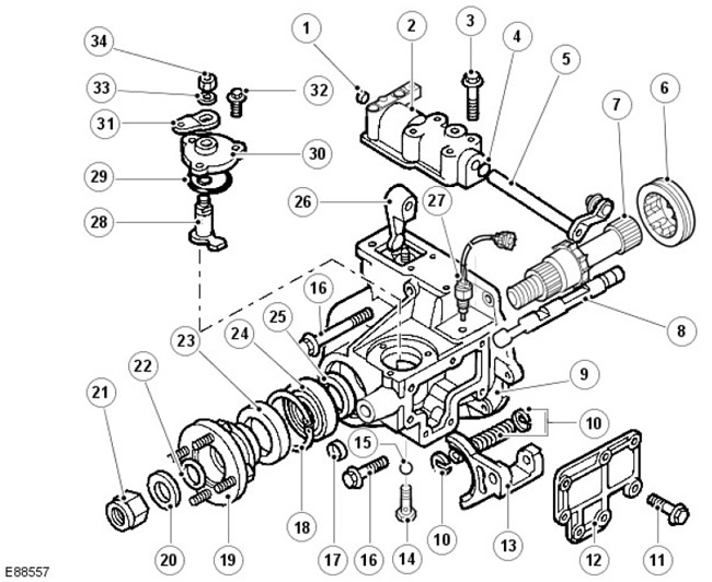
| Pos. | Spare part number | Name |
| 1 | - | Hollow plug |
| 2 | - | High/Low Range Cross Shaft Housing |
| 3 | - | High/Low Range Cross Shaft Housing Bolt |
| 4 | - | O-ring seal |
| 5 | - | High/low range cross shaft and cable ball end lever |
| 6 | - | Cam clutch |
| 7 | - | Front axle drive shaft |
| 8 | - | Differential lock selector shaft |
| 9 | - | Front axle drive shaft housing |
| 10 | - | Differential lock spring and clamps |
| 11 | - | Cap bolt |
| 12 | - | Lid |
| 13 | - | Differential lock selector fork |
| 14 | - | Differential locking device retaining plug and spring |
| 15 | - | Differential locking device locking ball |
| 16 | - | Front axle drive shaft housing bolt |
| 17 | - | Plug |
| 18 | - | Retaining ring |
| 19 | - | Drive shaft flange and mudguard |
| 20 | - | Steel washer |
| 21 | - | Self-locking nut |
| 22 | - | Felt pad |
| 23 | - | Seal |
| 24 | - | Drive shaft bearing |
| 25 | - | Bearing spacer |
| 26 | - | High/Low Range Selector Finger |
| 27 | - | Differential lock indicator switch |
| 28 | - | Differential lock selector pin and shaft |
| 29 | - | O-ring seals |
| 30 | - | Differential lock selector housing |
| 31 | - | Selector |
| 32 | - | Housing bolt |
| 33 | - | Washer |
| 34 | - | Self-locking nut |
The front axle drive shaft housing carries:
- front axle drive shaft and flange
- housing and selector
- fork and shaft of the differential lock selector
The front axle drive shaft is supported in the housing by a single bearing and is splined to the differential front sun gear.
Housing and selector assembly
The high/low range cross shaft is located in a housing which is bolted to the top of the drive shaft housing and connects to the high/low range pin which is located in a groove in the selector shaft.
Fork and shaft of the differential lock selector
The differential lock selector housing is bolted to the top of the front drive shaft housing. The selector pin passes through the housing and is located in a groove in the differential lock selector shaft. The differential lock selector shaft passes through the selector fork, which is located below a plate bolted to the side of the drive shaft housing. When the keys of the sleeve and the rear differential shaft are aligned with each other, the selector fork engages the cam clutch sleeve with the rear differential shaft. A spring-loaded detent ball mounted in the drive shaft housing is located in grooves on the shaft.
Rear axle drive shaft housing
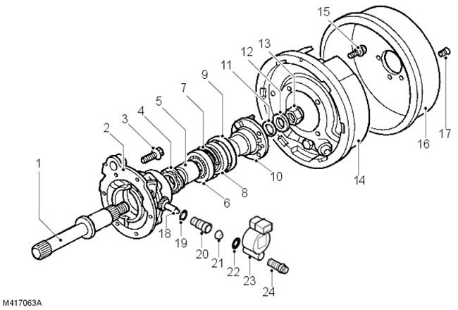
| Pos. | Spare part number | Name |
| 1 | - | Rear axle drive shaft |
| 2 | - | Rear axle drive shaft housing |
| 3 | - | Rear axle drive shaft housing bolt |
| 4 | - | Speedometer pinion |
| 5 | - | Spacer |
| 6 | - | Drive shaft bearing |
| 7 | - | Retaining ring |
| 8 | - | Seal |
| 9 | - | Mudguard |
| 10 | - | Drive shaft flange |
| 11 | - | Felt pad |
| 12 | - | Steel washer |
| 13 | - | Self-locking nut |
| 14 | - | Transmission brake shield |
| 15 | - | Transmission brake shield bolt |
| 16 | - | Transmission brake drum |
| 17 | - | Countersunk head screw |
| 18 | - | Speedometer driven gear |
| 19 | - | O-ring seal |
| 20 | - | Speedometer driven gear housing |
| 21 | - | Pad |
| 22 | - | O-ring seal |
| 23 | - | Vehicle speed sensor (if it is installed) |
| 24 | - | Hexagon socket head cap screw (if available) |
The rear axle drive shaft housing contains the rear axle drive shaft and flange, as well as the drive and driven gears of the speedometer. A transmission brake with a mechanical drive is connected to the housing, where the brake drum is attached to the output flange.
The rear axle drive shaft is supported in the corresponding housing by a single bearing and has a splined connection with the rear shaft of the differential. The drive shaft also contains a speedometer drive gear, which is in engagement with the speedometer driven gear located in the housing of the rear axle drive shaft.
The switch for the differential lock indicator lamp, activated by movement of the fork and selector shaft, is screwed into the upper part of the drive shaft housing.
Lubrication
Lubrication is provided by splash, filler/inspection plugs and drain plug are located in the main body.
The increase in internal pressure caused by thermal expansion and contraction is avoided by using a plastic vent pipe, through which gases from the internal volume of the box are discharged to the atmosphere. This pipe is connected to the upper part of the high/low range selector housing and, rising continuously upwards, passes to the engine compartment, where its open end is attached to the engine cylinder block.
Job
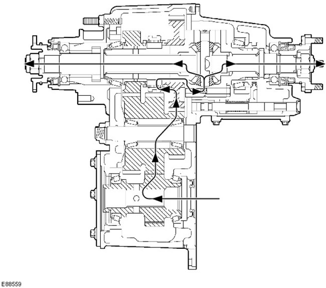
Power Flow - Transfer Case in LOW Range
Power Flow - Transfer Case in HIGH Range
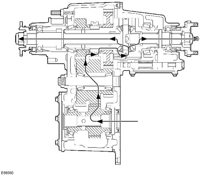
The transmission drive shaft transmits power to the secondary shaft pinion, which is in constant engagement with one of the intermediate gears. The intermediate gears are in constant engagement with the high and low range output gears, which are located on the rear differential shaft.
Power is transmitted to the drive shafts via the differential assembly by locking the high or low range gears to the rear differential shaft. This is accomplished via the high/low range selector fork, sleeve and splined hub.
Comments on this article