After the vehicle speed is less than 20 km/h for 12 minutes, the system switches to "parking mode". In parking mode, the tire pressure sensors transmit a coded signal to the module every 13 hours. If the tire pressure drops by more than 0.6 bar, the sensor transmits the signal more frequently.
In the parking mode, the spare tire pressure sensor transmits signals every 132 hours in the same way as the working wheel sensors. If the tire pressure drops by more than 0.6 bar, the sensor transmits a signal more frequently.
Once each sensor has responded to the low frequency signal from the TPMS module, the sensor is assigned a position on the vehicle and is monitored in that position for the remainder of the current driving cycle.
After the vehicle has been parked for more than 15 minutes and driven at a speed greater than 20 km/h, the initiators are activated in turn for 6 seconds on all vehicles except vehicles for the North American market and for 18 seconds on vehicles for the North American market in the following order:
- Left front
- Pause 6 seconds (for the TPMS module to receive a response signal from the tire pressure sensor)
- Right front
- Pause 6 seconds
- Right rear
- Pause 6 seconds
- Left rear
- Pause 6 seconds.
Each tire pressure sensor responds to the module in turn so that the module can determine the location of the sensors and begin the drive cycle. This process is repeated up to three times, or less if the sensor locations are already known to the module. This process is called "automatic location detection" and takes 7-8 minutes on North American market vehicles and 3-4 minutes on all other vehicles. During this time, the tire pressure sensors transmit signals at regular intervals, which are 15 seconds for North American market vehicles and 5 seconds for all other vehicles. Thereafter, during the drive cycle, the tire pressure sensors transmit signals every 60 seconds and whenever a change in tire pressure is detected until the vehicle comes to a stop and the system enters Park mode.
Once the position of the wheel has been detected, the initiators stop firing until the vehicle has been stationary for 15 minutes. While the vehicle is moving, each tire pressure sensor transmits a signal at 1-minute intervals. This allows the tire pressure to be monitored. There are two warning levels: a yellow indicator lights up when the pressure drops by 25%, and a corresponding message appears on the instrument cluster message center display when the pressure drops by 35%. The message center display also shows additional information about the position of the flat tire.
Initiator
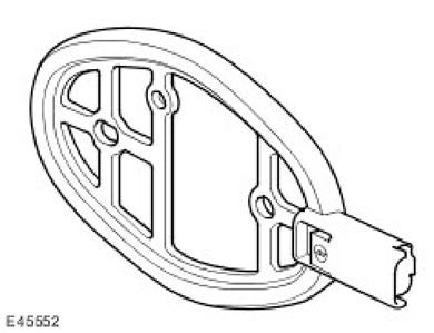
The initiators are located near the front of the front wheel arches and near the back of the rear wheel arches and are secured with two rivets. The TPMS system has four initiators. Each initiator has a connector through which it is connected to the body wiring harness.
The initiator is a passive low-frequency transmitter. Each initiator supports the function of automatic detection of the tire position on the vehicle and transmits the corresponding data to the TPMs module.
The TPMS module activates each initiator in turn using low-frequency pulses. The corresponding tire pressure sensor detects the low-frequency pulses and transmits a response radio frequency signal containing its data. The TPMS module receives this data via an internal high-frequency antenna. The module can then determine which sensor is transmitting data and locate it on the vehicle.
Tire pressure sensor
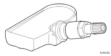
The TPMS system uses "active" tire pressure sensors mounted on each wheel inside the tire. The sensor is attached to the wheel by the valve. The sensors transmit radio frequency signals at 315 or 433 MHz, depending on market requirements.
The sensors periodically measure the pressure and temperature of the air in the tires. The pressure and temperature data are periodically sent to the vehicle's radio frequency receiver.
Tire pressure sensors are stand-alone devices and have no external electrical connections.
To avoid damaging the sensors, follow the instructions in the "Replacing Tires" section of this chapter. If you replace a sensor, also replace the nut, seal and washer and tighten the sensor to the torque specified in the Workshop Manual.
The radio frequency signal of each sensor contains a unique identification code by which the TPMS module can identify the tire on the vehicle. In case of replacing the sensor on the "working" wheel, the identification data of the new sensor will be received during the first drive at a speed of 20 km/h for 15 minutes. If the new sensor is installed on the spare tire, its identification data must be programmed into the TPMS module using T4, otherwise this wheel will not be monitored. The code is located on the label of the new wheel and tire assembly and is also printed on the packaging of each sensor.
In addition, you can program the spare wheel data by using it as a "working" wheel for 15 minutes while driving at a speed of 20 km/h.
To conserve battery power, the tire pressure sensor transmits data at different intervals when stationary and when driving. The wheel speed at which the transition from low data transmission rate occurs (in the parking lot) on high (while moving) very small, which is important when driving slowly off-road.
(The article was copied from a resource: www.LRman.ru)
TPMS switch
NOTE: The TPMS switch is not installed on North American market vehicles. North American market vehicles do not have the desired pressure selection feature.
The TPMS switch is a momentary push button located on the center console switch panel next to the hazard warning switch.
The TPMS switch is used by the driver to set the desired tire pressure for the vehicle's "normal load" and "high load" tires. The switch allows you to select one of two modes.
On the front of the TPMS switch is a status LED that informs the driver whether the desired pressure mode is selected for "normal load" or "high load". The LED is lit when the "normal load" mode is selected. The LED is off when the "high load" mode is selected.
The status LED has two modes of illumination - day and night. The brightness of the LED is determined by the TPMS module based on data received via the vehicle's CAN bus.
The switch is used to change modes. The ignition key must be in position II. If the TPMS is in the "normal load" mode, pressing and holding the switch will change the required pressure values to the "high load" mode values. The LED will go out and the message 'Tire Pressures High Load Condition' will flash on the instrument cluster for 5 seconds. (tire pressure mode for increased load). This mode will work until the driver turns it off.
To switch from the "high load" mode to the "normal load" mode, the ignition key must be set to position II and the switch must be pressed and held. This will set the required pressure values corresponding to the "normal load" mode. The switch LED will light and the message 'Tire Pressures Normal condition' will appear on the instrument panel for 5 seconds. (tire pressure mode for normal load).
Comments on this article