Contents: Connector C1537 ⇩ Connector C2447 ⇩ CAN signals (Controller Area Network…⇩ Received messages ⇩ Messages transmitted ⇩
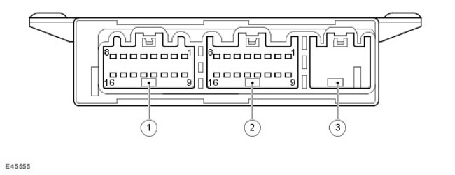
| Item name | Spare part catalog number | Description |
| 1 | - | Connector C2447 |
| 2 | - | Connector C1537 |
| 3 | - | Not used |
Two connectors provide an interface between the TPMS module and external devices of this system. The third connector socket on the TPMS module is not used.
The following tables list the signals and power lines that correspond to each connector pinout.
Connector C1537
| Contact No. | Description | Login/Logout |
| 1 | Not used | - |
| 2 | Low Speed CAN Bus - Input | Login/Logout |
| 3 | High Speed CAN Bus - Input | Login/Logout |
| 4 | Not used | - |
| 5 | TPMS Switch LED Power Supply | Exit |
| 6 | Not used | - |
| 7 | TPMS switch | Entrance |
| 8 | Ignition supply 12V | Entrance |
| 9 | Not used | - |
| 10 | Low Speed CAN Bus - Output | Login/Logout |
| 11 | High Speed CAN Bus - Output | Login/Logout |
| 12 | Weight | Entrance |
| 13-15 | Not used | - |
| 16 | Continuous 12V power supply from battery | Entrance |
Connector C2447
| Contact No. | Description | Login/Logout |
| 1-4 | Not used | - |
| 5 | Left rear initiator - positive (+) signal | Exit |
| 6 | Left rear initiator - negative (-) signal | Exit |
| 7 | Right rear initiator - positive (+) signal | Exit |
| 8 | Right rear initiator - negative (-) signal | Exit |
| 9-12 | Not used | - |
| 13 | Left Front Initiator - Positive (+) Signal | Exit |
| 14 | Left Front Initiator - Negative (-) Signal | Exit |
| 15 | Right Front Initiator - Positive (+) Signal | Exit |
| 16 | Right Front Initiator - Negative (-) Signal | Exit |
CAN signals (Controller Area Network - local area network of controllers)
The TPMS module transmits and receives digital messages over the medium-speed CAN bus. The received messages are used to control the operation of the TPMS. The transmitted messages contain information about the TPMS status and commands to turn on the indicators and/or display messages on the instrument cluster message center display.
Received messages
The TPMS module receives the messages listed in the following table.
| Message | Transmitter |
| Car speed | ABS module |
| Corrected ambient temperature | ATC module |
| Condition of side lights | CJB |
| Ignition switch status | CJB |
| Odometer readings | Instrument panel |
| Timer readings | Instrument panel |
| Voltage level in the vehicle's electrical system | Instrument panel |
| Engine Crankshaft Relay Status | ECM |
| Physical diagnostic request | T4 |
| Functional diagnostic request | T4 |
| Engine condition | ECM |
| Identification information of the basic vehicle configuration | Instrument panel |
| Vehicle configuration parameters | Instrument panel |
Messages transmitted
The TPMS module transmits the messages shown in the following table.
| Message | Receiver |
| TPMS diagnostic response signal | T4 |
| Request to turn on the red TPMS indicator when the tire pressure drops by 35%. | Instrument panel |
| Request to turn on the yellow TPMS indicator when the tire pressure drops by 25% | Instrument panel |
| TPMS Sound Signal | Instrument panel |
| TPMS Message Display Request | Instrument panel |
[The original text was published on the website: LRman.ru]
Comments on this article