Contents: Dismantling ⇩ Assembly ⇩
Before disconnecting the battery, make sure that all requirements and conditions contained in the section on disconnecting the battery are met.
GENERAL INFORMATION, Precautions when working with electrical equipment.
Dismantling
1. Disconnect the negative battery terminal.
2. Remove the air intake hose.
ENGINE MANAGEMENT SYSTEM: V8 engine, REPAIR WORK, Hose connecting the air flow sensor to the throttle body.
3. Remove the left ignition coil cover.
ENGINE MANAGEMENT SYSTEM: V8 engine, REPAIR WORK, Left-hand ignition coil cover.
4. Remove the right ignition coil cover.
ENGINE MANAGEMENT SYSTEM: V8 engine, REPAIR WORK, Right bank ignition coil cover.
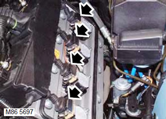
5. Disconnect the connectors from the ignition coils.
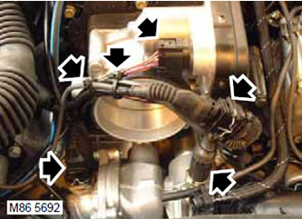
6. Disconnect the connectors from the throttle body, thermostat heater, camshaft position (CMP) sensor and coolant temperature (ECT) sensor. Cut the 2 plastic ties and release the engine harness.
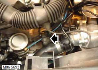
7. Disconnect the connectors from the variable valve timing (VCC) solenoids.
8. Release the VCC solenoid valve connector from the clamp.
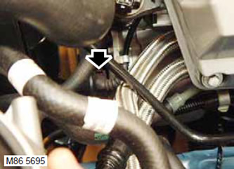
9. Disconnect the connector from the generator.
10. Release the generator harness from the 4 clamps.
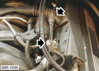
11. Disconnect the connector from the knock sensor (KS) and camshaft position sensor (CMP).
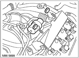
12. Unscrew the 2 bolts securing the fuel injector wiring harness to the fuel rail.
13. Release the vacuum receiver and mounting bracket from the left fuel injector wiring harness mounting stud.
14. Remove the fuel pipe and bracket from the left fuel injector wiring harness mounting stud.
15. Release the generator harness from the two clamps on the upper engine casing brackets.
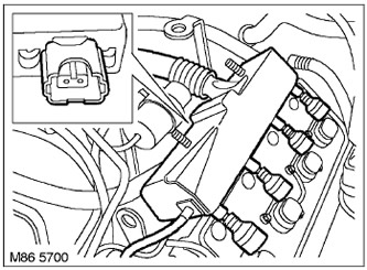
16. Disconnect the pads from the fuel injectors.
17. Disconnect the engine harness from the clamps and move it away from the valve cover.
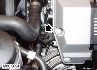
18. Disconnect the connector from the fuel vapor canister purge solenoid valve.
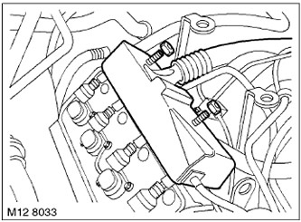
19. Unscrew the 2 nuts securing the engine harness to the intake manifold.
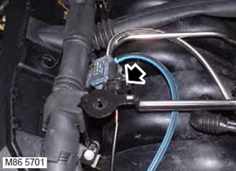
20. Disconnect the electrical connector from the SAI solenoid valve (afterburning systems).
21. Remove SAI valve (afterburning systems) from the right stud of the injector harness.
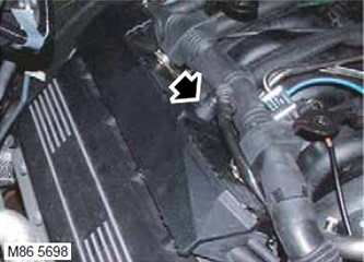
22. Disconnect the connector from the knock sensor.
23. Remove the washer from the fuel injector wiring harness stud.
24. Disconnect the pads from the fuel injectors.
25. Route the fuel injector wiring harness to its location.
26. Remove the air intake receiver.
HEATING AND VENTILATION, REPAIR WORKS, Air intake box.
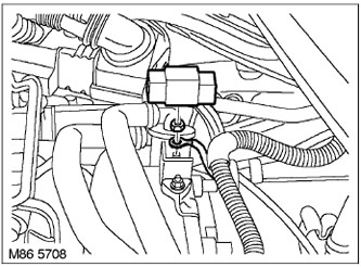
27. Remove the terminal cover, unscrew the nut and disconnect the 2 wires from the pole piece.
28. Release residual pressure in the fuel supply system.
V8 ENGINE FUEL SUPPLY SYSTEM, ADJUSTMENTS AND MAINTENANCE, Relief of residual pressure.
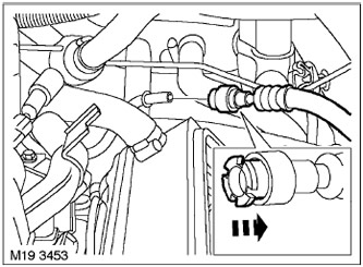
29. Disconnect the fuel supply hose from the fuel rail.
CAUTION: Always plug the fittings and holes to protect the system from dirt.
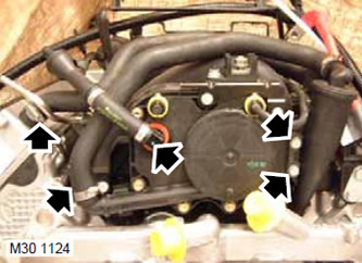
30. Unscrew 2 clamps and disconnect 2 ventilation hoses.
31. Loosen the clamp and disconnect the brake system vacuum hose.
32. Unscrew the 2 bolts securing the oil separator to the manifold.
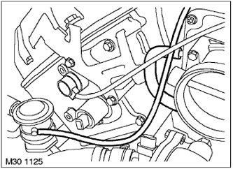
33. Loosen the clamp and disconnect the vacuum hose from the canister purge solenoid valve. Disconnect the SAI vacuum tube. (afterburning systems).
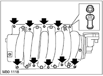
34. Unscrew the 10 nuts securing the intake manifold to the cylinder heads and remove the 10 spacer bushings.
35. Move the brake booster vacuum line to the side.
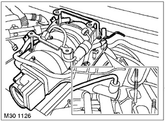
36. Lift the intake manifold and disconnect the ventilation hoses.
37. Remove the intake manifold and discard the 4 gaskets.
NOTE: If disassembly was performed only to provide access to other system components, no further disassembly operations should be performed.
38. Disconnect the vacuum tube and remove the solenoid valve.
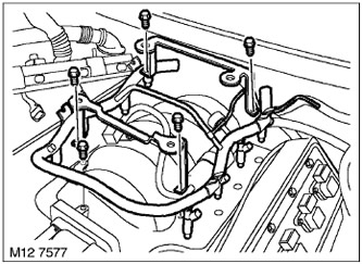
39. Remove the 4 bolts securing the upper engine casing brackets from the intake manifold.
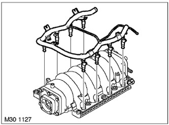
40. Loosen the bolt securing the fuel rail to the intake manifold and remove the rail with injectors.
41. Remove the lower O-rings from the injectors and discard them.
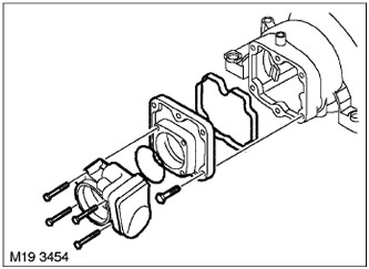
42. Unscrew the 4 bolts securing the throttle pipe to the intake manifold and remove the throttle pipe.
43. Remove the O-ring from the throttle body and discard it.
44. Unscrew the 6 bolts securing the front cover to the intake manifold and remove the front cover.
45. Remove and discard the O-ring.
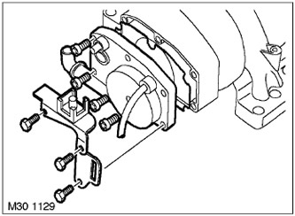
46. Unscrew the 3 bolts securing the two brackets to the rear cover of the manifold.
47. Remove 2 brackets.
48. Unscrew the 4 bolts securing the rear cover to the intake manifold and remove the cover.
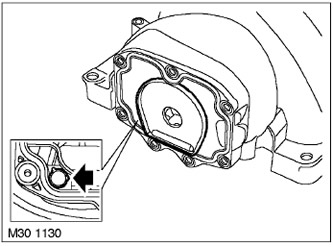
49. Remove and discard the O-ring.
50. Press the retainer shoulders and remove the ventilation tube from the intake manifold.
Assembly
1. Connect the ventilation tube to the intake manifold.
2. Install a new O-ring onto the back cover.
3. Install the rear cover onto the intake manifold and tighten the 4 bolts. Tightening torque 10 N·m.
4. Install 2 brackets and screw in 3 mounting bolts. Tightening torque 10 Nm.
5. Install a new O-ring onto the front cover.
6. Install the front cover onto the intake manifold and tighten the 6 bolts. Tightening torque 10 N·m.
7. Install a new seal on the throttle body.
8. Install the throttle body onto the intake manifold and tighten the 4 bolts. Tightening torque 10 N·m.
9. Lubricate the new O-rings and install them on the injectors.
10. Insert the injectors with the rail into the intake manifold and screw in the bolt.
11. Install 2 new brackets on the manifold and tighten the 5 bolts. Tightening torque 10 Nm.
12. Install the solenoid valve and connect the vacuum tube.
13. Install 4 new gaskets and install the intake manifold.
14. Connect the ventilation hose and place the manifold on the studs.
15. Connect the vacuum pipe of the brake booster.
16. Insert 10 spacers and tighten 10 manifold mounting nuts. Tightening torque 15 Nm.
17. Connect the vacuum hose to the front intake manifold cover.
18. Connect the brake system vacuum hose and secure it with a clamp.
19. Connect 2 ventilation hoses and secure them with two clamps.
20. Wipe the fuel hose connectors.
21. Connect the fuel supply hose to the fuel rail.
22. Connect the 2 wires to the pole piece, tighten the terminal nut and install the terminal cover.
23. Install the air intake receiver in place.
HEATING AND VENTILATION, REPAIR WORKS, Air intake box.
24. Connect the fuel injector wiring harness.
25. Install the washer onto the fuel injector harness mounting stud.
26. Install the afterburner system vacuum solenoid valve onto the right fuel injector harness mounting stud.
27. Install the 2 nuts securing the fuel injector harness to the intake manifold and tighten them.
28. Connect the connector to the fuel vapor canister purge valve.
29. Install the engine harness onto the bracket and secure it with clamps.
30. Connect the fuel injector wiring harness connector.
31. Attach the alternator harness to the two clamps on the upper engine cover.
32. Install the fuel hose with the bracket onto the left row injector harness mounting stud.
33. Attach the vacuum receiver with the bracket to the left-hand injector harness mounting stud.
34. Install the 2 nuts securing the fuel injector harness to the intake manifold and tighten them.
35. Connect the connector to the knock sensor.
36. Connect the connector to the camshaft position (CMP) sensor.
37. Secure the generator wiring harness with 4 fasteners.
38. Connect the generator connector.
39. Connect the connector to the fuel vapor canister purge valve.
40. Secure the VCC harness connector to the clamp.
41. Connect the connectors to the valve body solenoids.
42. Install new plastic ties and secure the harness.
43. Connect the connector to the camshaft position (CMP) sensor.
44. Connect the connector to the throttle body.
45. Connect the connector to the coolant temperature (ECT) sensor.
46. Place the connectors on the ignition coils.
47. Replace the ignition coil cover.
ENGINE MANAGEMENT SYSTEM: V8 engine, REPAIR WORK, Right bank ignition coil cover.
48. Replace the ignition coil cover.
ENGINE MANAGEMENT SYSTEM: V8 engine, REPAIR WORK, Left-hand ignition coil cover.
49. Reinstall the air intake hose.
ENGINE MANAGEMENT SYSTEM: V8 engine, REPAIR WORK, Hose connecting the air flow sensor to the throttle body.
50. Connect the negative battery terminal.
Comments on this article