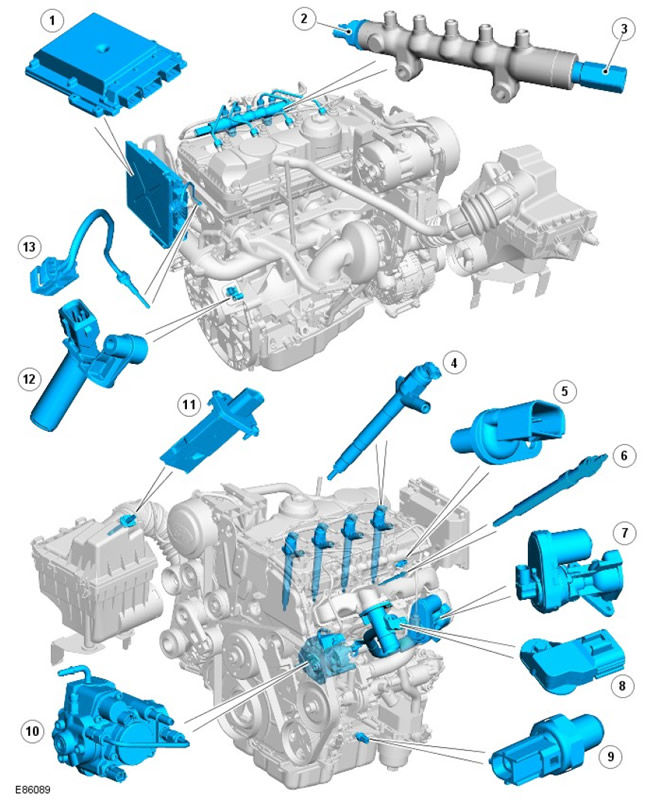
Arrangement of elements, sheet 1
| Pos. | spare part no | Name |
| 1 | - | the engine control unit (ECM) |
| 2 | - | Fuel pressure sensor |
| 3 | - | Pressure limiting valve |
| 4 | - | Injectors |
| 5 | - | Camshaft position sensor (CMP) |
| 6 | - | glow plugs |
| 7 | - | Exhaust gas recirculation valve (EGR) |
| 8 | - | Manifold absolute pressure sensor (MAP) |
| 9 | - | Oil pressure switch |
| 10 | - | Fuel pump |
| 11 | - | mass air flow sensor (MAF) /intake air temperature (IAT) |
| 12 | - | crankshaft position sensor (CKP) |
| 13 | - | Head temperature sensor (CHT) |
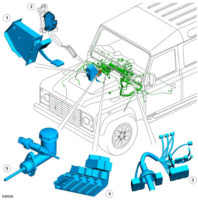
Arrangement of elements, sheet 2
| Pos. | spare part no | Name |
| 1 | - | Brake pedal sensor |
| 2 | - | Sensor Accelerator Pedal Position Sensor (APP) |
| 3 | - | battery electrical junction box (BJB) |
| 4 | - | central fuse box (CJB) |
| 5 | - | Clutch position sensor |
Review
The engine management system is controlled by the ECM and is able to control, adjust and fine-tune fuel injection. The ECM utilizes input from various sensors and precisely controls the actuators to ensure optimum dynamic performance under all driving conditions.
The ECM controls fuel delivery to all 4 cylinders via a common rail fuel injection system (Common Rail). The Common Rail system consists of a fuel manifold that holds very high pressure fuel and four electronically controlled injectors. The fuel manifold is located in close proximity to the injectors, so that at any time, on each of the injectors, the pressure set in the system develops.
The ECM uses the control-by-wire principle for acceleration control. There is no physical connection between the engine and the accelerator pedal. The desired power change is signaled to the ECM by two APP sensor potentiometers. Two signals are needed to determine the position of the pedal, the speed of its movement and the direction of movement of the ECM. The ECM then uses this data, along with other engine information from other sensors, to provide optimal engine response.
ECM processes information from the following sources:
- CKP sensor
- Sensor (CMP)
- Air temperature and pressure in the intake manifold
- cylinder head temperature
- Oil pressure
- Intake air flow and temperature
- Fuel temperature
The ECM provides output signals to control the following sensors and actuators:
- nozzles
- Viscous fan clutch solenoid
- Turbocharger with electronic vane control
- Control valve (regulator) fuel pressure
- Fuel volume control valve
- Electronic Exhaust Gas Recirculation (EGR)
- glow plugs
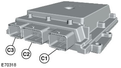
The engine control unit
| Pos. | spare part no | Name |
| C1 | - | Connector 1 |
| C2 | - | Connector 2 |
| C3 | - | Connector 3 |
The ECM is connected to the on-board network through three connectors. The ECM includes processors for data processing and memory chips. The output signals generated by the final amplifier of the ECM are sent to the actuators through the line of the controlled «masses». The ECM transistor switch circuits generate heat dissipated by the enclosure during normal operation. Some sensors receive voltage regulated by the ECM. This measure avoids signal distortion caused by a voltage drop when the engine is cranked by the starter.
The ECM performs self-diagnostic procedures and stores fault codes in memory. These DTCs and diagnostic mode can be accessed using a Land Rover approved diagnostic system. If the ECM is due for replacement, a new ECM is supplied "clean" and must be configured to match the vehicle using a Land Rover approved diagnostic system. reprogrammable electrically erasable ROM (EEPROM) allows the ECM to be reconfigured to meet changing operating and adjustment requirements up to 14 times using recommended diagnostic tools. If a 15th reprogramming is required, the ECM must be replaced. Current engine adjustment data can be accessed using the Land Rover approved diagnostic system.
When a new ECM is installed, it must also be synchronized with the theft deterrent control module using a Land Rover approved diagnostic system. ECMs must not be transferred from vehicle to vehicle.
The ECM is connected to sensors that monitor engine operation. By processing the sensor signals, the ECM decides on the actions necessary to maintain the optimal engine operating mode in terms of driving parameters, fuel consumption and exhaust gas toxicity. During programming, the ECM stores instructions with an engine control algorithm called a control strategy. The ECM memory also contains multi-parameter characteristics ("cards"), used as the basis for fuel management and the emission control system. Comparing information received from sensors with data "kart", the ECM is able to generate control signals. The ECM implements an adaptive strategy that updates the system when its elements change due to manufacturing tolerances or aging.
The ECM receives a vehicle speed signal. The vehicle speed signal plays an important role in the ECM control strategy. The frequency of these signals depends on the speed of movement.
Crankshaft position sensor (CKP)
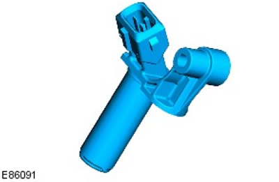
The CKP sensor is located at the left rear of the cylinder block. The tip of the sensor is in the plane of rotation of the magnetic disk mounted on the crankshaft. The driving disk is pressed onto the end of the crankshaft. To obtain the correct signal in phase, the driving wheel must be correctly aligned with the crankshaft. At the output of the sensor, a rectangular signal is formed with a frequency proportional to the frequency of rotation of the crankshaft.
The ECM monitors the CKP sensor signal and detects overspeed. The ECM counteracts overspeed by phasing out the functions associated with shaft rotation. The CKP sensor is a Hall effect sensor. The sensor responds to changes in the magnetic field that occur when the magnetized setting wheel rotates.
The impulse wheel has two missing teeth corresponding to 12°crankshaft revolution. A gap of two missing teeth is used to determine the angular position of the crankshaft.
The signal generated when the gap in the drive wheel passes the sensor is used by the ECM to determine the position of the crankshaft. For the correct formation of the sensor signals supplied to the ECM, the size of the air gap between its end face and the crown of the toothed disk is of great importance. The recommended air gap between the CKP sensor and the drive wheel is 0.4 mm - 1.5 mm.
The ECM uses the CKP sensor signal to perform the following functions:
- Synchronization.
- Determination of the moment of the start of fuel supply.
- Fuel pump relay circuit energized (after pre-pumping).
- Formation of crankshaft speed signals and their transmission over the bus CAN data transfer protocol (CAN) for use in other systems.
CMP
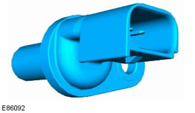
The CMP sensor is located on the left side of the cylinder head towards the rear. The tip of the sensor passes through the wall and senses the passage of the driving rotor located behind the camshaft pulley.
The Hall effect camshaft position sensor is used by the ECM at engine start to synchronize the ECM with the CKP sensor signal. The ECM uses the CMP camshaft position sensor to identify the 1st cylinder to establish the correct fuel order. Once the ECM has learned the fuel order, the CMP sensor signal is no longer used.
The ECM provides 5 volts to the CMP sensor. The remaining two connections to the ECM provide ground and signal output.
If a sensor fails, a fault code is stored in the ECM. There are two types of failures: signal frequency too high or no signal at all. The malfunction recorded by the ECM may also be related to the complete absence of the crankshaft position signal or to the distortion of the form of this signal. Both possibilities must be checked to determine the cause of the failure.
If a CMP sensor failure occurs while the engine is running, engine operation will continue, however, the ECM will disable the boost pressure control system. After stopping the engine, restarting it (even though the starter is turning the engine) will not be possible as long as the fault code is in memory.
Glow plugs
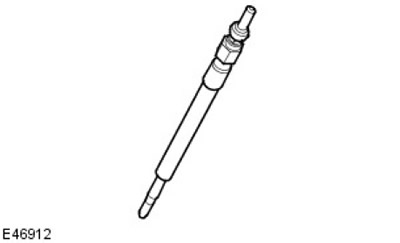
Four glow plugs are installed in the cylinder head on the intake side. Glow plugs and the relay that controls them are essential to ensure the desired starting performance of the engine. When starting a cold engine, the spark plugs heat the air in the combustion chamber, helping to ignite the fuel. The use of glow plugs allows you to reduce the starting fuel supply and, accordingly, reduce the amount of black smoke. In addition, the use of candles makes it possible to reduce the starting angle of the injection advance, which reduces the rigidity of the engine, especially when it is cold, idling.
The operation of glow plugs is divided into three phases:
- Preheat
- Work when scrolling the crankshaft
- post-glow
The main part of the candle is a tubular heating element protruding into the combustion chamber. The heating element contains an incandescent coil embedded in magnesium oxide powder. The heater coil is located at the tip of the tubular heating element. Behind the heater coil is a serially connected control coil. The ballast coil limits the heating of the heating coil, preventing it from overheating.
Preheat is the period of time the spark plugs are on before the starter is turned on. The length of the preheat period is controlled by the ECM based on the engine coolant temperature (ECT) and battery voltage. If the ECT sensor fails, the ECM defaults to the values it receives from the IAT sensor. Preheating time increases with low coolant temperature and a partially discharged battery.
Post-glow is the period of time the candles work after the engine is started. Postglow duration is controlled by the ECM based on data from the ECT sensor. Afterglow reduces engine noise ("softens" the working process), improves idling uniformity and reduces hydrocarbon emissions.
When the ignition key is turned to position II, the glow plug warning lamp lights up on the instrument panel. The glow plug indicator works independently of the glow plugs, so it does not turn on when the crankshaft is cranked and after the engine is started. With the glow plug indicator switched off, the glow plugs themselves can continue to work during the last two phases.
If the glow plugs fail, there is difficulty starting the engine and increased smoke after starting the engine.
The glow plug warning light is also used for the second function in the EDC system. In the event of a serious malfunction of the EDC system, the glow plug warning lamp will remain on until the malfunction is corrected. The driver should have the Land Rover dealer check the engine management system as soon as possible.
Nozzles
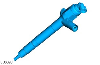
4 electronically controlled nozzles (according to the number of engine cylinders) located along the vertical axis of the cylinders, between the four valves. The ECM divides the injectors into 2 rows of 4 cylinders.
Fuel under high pressure is supplied to the nozzles from the fuel manifold and sprayed by them into the combustion chambers in a finely dispersed form. The ECM controls the operation of each injector separately by detecting pulse width modulation (PWM) the order of their work and the size of the cyclic feed. Each injector receives a 12 V supply from the ECM. The engine control unit, based on the recorded control characteristics and sensor signals, calculates the exact moment of the preliminary and main fuel supply phases for each cylinder. If the battery voltage drops to 6-9 V, the operation of the injector is limited, which worsens the environmental parameters and engine idling, and also affects the speed range of the engine. Injector failure may be accompanied by the following symptoms:
- Misfires
- Rough idle
- Deterioration of the energy performance of the engine
- Increase in fuel consumption
- Difficult start
- Increased opacity of exhaust gases
The ECM monitors each injector's power circuit for shorts or open circuits, each injector's solenoid coil, and the transient current characteristic of the ECM itself. When a malfunction is detected, the ECM logs an error for the injector being tested.
CHT sensor
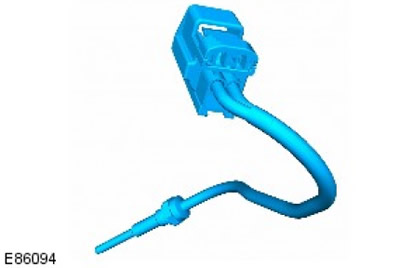
The CHT sensor is located in the upper hose at the outlet of the coolant manifold. The ECT coolant temperature sensor provides the ECM and instrument cluster with information about the engine coolant temperature.
The temperature signal is used by the ECM to implement the following control functions:
- Fuel Cycle Calculation
- Engine power limitation due to excessively high coolant temperature
- Cooling Fan Control
- Regulation of duration of work of glow plugs.
The instrument panel uses temperature information to operate the temperature gauge. The CHT signal is also transmitted by the instrument panel on the CAN bus for use by other systems.
The ECM CHT sensor circuit consists of an internal voltage divider circuit with an NTC resistance thermistor (NTC). As CHT increases, the resistance of the sensor decreases, and vice versa. The output signal of the sensor is a change in voltage, which occurs due to an increase in the strength of the current passing through "earth", with temperature change.
ECM compares signal voltage with data "cards" and regulates cycling for optimal driving performance under all conditions. Due to fuel condensation on the cold walls of the combustion chamber, the engine requires increased supply at low coolant temperatures.
To enrich the air/fuel mixture, the ECM extends the open time of the injector. As the engine warms up, the mixture becomes leaner.
The ECM voltage divider supplies the sensor with a reference voltage of 5 V. «Weight» The sensor is also connected to the ECM, which, based on the measured current, determines the resistance of the sensor corresponding to the temperature of the coolant.
The table summarizes the CHT values and the corresponding resistance and voltage values.
Characteristics of the coolant temperature sensor
| Temperature, degrees Celsius | Resistance, kOhm | Voltage, V |
| -40 | 925 | 4,54 |
| -30 | 496 | 4,46 |
| -20 | 277 | 4,34 |
| -10 | 160 | 4,15 |
| 0 | 96 | 3,88 |
| 10 | 59 | 3,52 |
| 20 | 37 | 3,09 |
| 30 | 24 | 2,62 |
| 40 | 16 | 2,15 |
| 50 | 11 | 1,72 |
| 60 | 7,5 | 1,34 |
| 70 | 5,6 | 1,04 |
| 80 | 3,8 | 0,79 |
| 90 | 2,9 | 0,64 |
| 100 | 2,08 | 0,49 |
| 110 | 1,56 | 0,38 |
| 120 | 1,19 | 0,29 |
| 130 | 0,918 | 0,22 |
| 140 | 0,673 | 0,17 |
| 150 | 0,563 | 0,14 |
The following symptoms may accompany a CHT sensor failure:
- Difficulty starting from a cold state.
- Difficulty starting a hot engine.
- Deterioration of engine performance.
- The temperature gauge does not work or works with a large error.
In the event of a CHT sensor failure, the ECM defaults to a fluid temperature of 80°C for fuel control purposes. To protect the engine from overheating, the ECM will continuously turn on the cooling fan every time the ignition is turned on.
Oil pressure switch
The oil pressure switch, located in the oil cooler assembly, grounds the input signal to the instrument cluster if oil pressure is present. The sensor operates at a pressure of 0.15 to 0.41 bar.
Fuel rail pressure sensor
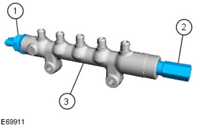
| Pos. | spare part no | Name |
| 1 | - | Fuel pressure sensor |
| 2 | - | Pressure limiting valve |
| 3 | - | fuel manifold |
The fuel rail pressure sensor is located at the front. The sensor measures the fuel pressure in the fuel rail. The sensor signal is used by the ECM to control the amount of fuel delivered to the fuel rail.
Fuel manifold relief valve
The fuel rail safety valve is located at the far end of the fuel rail. To prevent damage to the high pressure fuel system, this valve opens when the fuel pressure in the manifold reaches approximately 2000 bar. The ECM detects that the valve is open and sends a request for an emission control system malfunction warning light (MIL) on the instrument panel.
Once opened, the valve needs to be replaced.
Fuel temperature sensor
The fuel temperature sensor is located in the injection pump.
This sensor is an NTC sensor and is connected to the ECM with two wires. The ECM's fuel temperature sensor circuit includes an internal voltage divider that contains an NTC NTC thermistor. As the temperature increases, the resistance of the sensor decreases. The output signal of the sensor is a change in voltage, which occurs due to an increase in the strength of the current passing through "earth", with temperature change.
The ECM continuously monitors fuel temperature. If the fuel temperature exceeds 85°C, the ECM will enter a strategy to derate the engine. The amount of fuel supplied to the injectors is reduced and the fuel is allowed to cool. When switching to this mode, the driver may notice a decrease in power.
Further cooling of the fuel is provided in the heat exchanger, where the fuel, upon reaching a certain temperature, is directed by a bimetallic valve. On vehicles intended for delivery to countries with a hot climate, the heat exchanger is blown by an electric fan. The fan turns on and the thermostat turns off when the fuel reaches the set temperature.
The ECM also monitors the circuit between itself and the sensor for a short or open circuit. The ECM also monitors the 5V supply. When a fault occurs, the ECM stores the appropriate code in the ECM's memory and switches to standby mode, in which the ECM uses the stored pressure value.
If the ECM determines that the discrepancy between the pressure sensor signal and the value stored in the memory exceeds a preset value, then a DTC is stored in the ECM's memory. Depending on the amount of mismatch, the ECM will either limit the cycling, stop the engine immediately, or not allow the next start.
MAF sensor
The two MAF sensors are located on the intake duct just after the air filter. The sensor is housed in a plastic housing that is installed between the intake manifold and the air intake duct.
The MAF mass air flow sensor works on the principle of a hot film anemometer. There are two film sensitive elements in the printed circuit. The temperature of one element is maintained at the intake air temperature, for example 25°C. The second element is heated 200°C above the intake air temperature, i.e. up to 225°C. The air entering the engine passes through the MAF sensor and cools the film. The ECM measures the amount of current needed to maintain a set temperature difference of 200°C and uses this information to generate a highly accurate non-linear frequency-based air flow signal.
The output of the MAF sensor is a digital signal proportional to the mass air flow. The ECM uses this information, along with signals from other sensors and information stored in memory "kart" fuel supply, to accurately calculate the amount of fuel supplied to the cylinders. This signal is also used as a feedback signal for the EGR system.
The MAF sensor is supplied with 12 volts from the BJB and grounded through the ECM. The remaining two pins to the ECM provide signal output from the MAF and IAT intake air temperature sensors.
The ECM checks the mass air flow by calculating it as a function of engine speed. In the event that the calculated airflow rate is not plausible, the ECM will fallback to the stored values "cards" dependence of the average air consumption on the crankshaft speed. The mass flow value is then corrected for boost pressure, atmospheric pressure and air temperature.
If the MAF flow sensor fails, the ECM will go into standby control based on engine speed. If the MAF sensor signal fails, any of the following symptoms may be present:
- Difficult start
- Engine stall after start
- The engine responds sluggishly to the accelerator pedal
- Emission control system not working
- Idle speed control function does not work
- Deterioration of the dynamic characteristics of the engine.
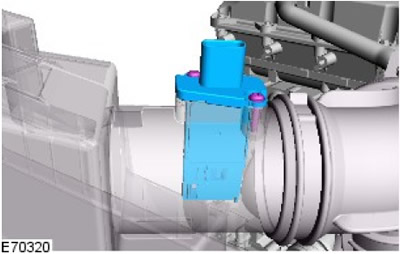
Temperature sensor and absolute pressure in the intake manifold (MAPT)
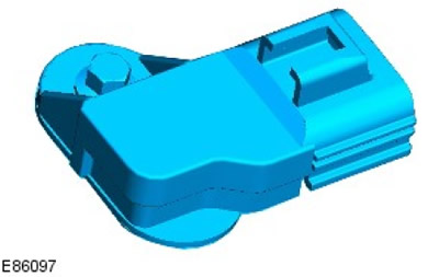
The MAPT sensor is located downstream of the turbocharger after the electric throttles. The sensor provides the ECM with a voltage signal based on intake manifold pressure. The MAPT sensor has a 3-pin connector connecting it to the ECM. The connector is used to supply the sensor with a reference voltage of 5 V from the ECM, transmit a signal to the ECM and connect the sensor to "weight".
MAPT sensors use a diaphragm transducer to measure pressure. The sensor signal is used by the ECM to perform the following functions:
- Support for boost pressure in the intake manifold.
- Reducing exhaust smoke when driving at high altitudes.
- Control of the EGR exhaust gas recirculation system.
- Management of the vacuum control module.
If a MAPT intake manifold absolute pressure/temperature sensor fails, the ECM defaults to 1013 mbar. In the event of a MAPT sensor failure, the following symptoms may be observed:
- Altitude corrector not working (black smoke from the exhaust)
- Boost pressure control does not work.
The boost pressure is controlled by a direct electric drive of the turbine nozzle apparatus. The control drive is located on the side of the turbocharger and is connected by rods to the guide vanes. The high torque electric motor has a built-in controller.
The electric drive can turn the blades at an angle of 60 degrees and can remember the extreme positions. Actuator operation is controlled by PWM pulses from the ECM.
EGR system
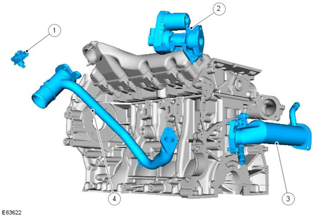
| Pos. | spare part no | Name |
| 1 | - | MAPT sensor |
| 2 | - | EGR block |
| 3 | - | EGR heat exchanger |
| 4 | - | Connecting pipeline |
The EGR system includes the following components:
- EGR modulator, 2 pcs.
- EGR heat exchanger, 2 pcs.
- Corresponding connecting pipes.
The EGR modulator and cooler are combined into one unit.
Each bank of cylinders has its own EGR modulator assembly with a heat exchanger located between the intake manifold and the cylinder head. The EGR heat exchanger is connected by hoses to the engine cooling system. The inlet part of the module is connected directly to its outlet manifold. The exhaust gases pass through the cooler and then through the actuator and metal piping into the throttle body. The EGR modulator is a solenoid valve controlled by the ECM. The ECM uses the EGR modulator to adjust the amount of exhaust gases sent to the intake to reduce the amount of nitrogen oxides and reduce the noise of the work process. The EGR system is activated only when the engine reaches operating temperature and when driving in steady state.
The EGR modulator is supplied with 12 V from the ECM. The modulator is controlled using a PWM signal. The PWM signal is generated by disconnecting / connecting the ground of the solenoid valve and sets the exact amount of exhaust gases supplied to the cylinders.
EGR modulators perform their full duty cycle every time the engine is started to clean up soot and carbon deposits.
If the EGR modulator fails, the EGR system stops working. The ECM monitors the EGR modulator solenoid for a short circuit and sets a fault code if a fault occurs. The modulator can be activated using a diagnostic tool recommended by Land Rover to test its functionality.
Pump capacity regulator (VCV)
The fuel manifold capacity regulator is built into the high pressure fuel pump. VCV valve bleeds excess fuel back to the fuel tank (or to the low pressure circuit), or directs to PCV. Excess fuel bleed avoids wasting power by the high pressure pump to unnecessarily compress the fuel in the manifold and concomitant heating of the fuel.
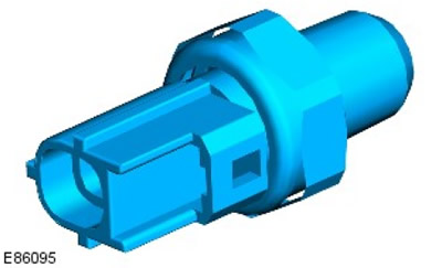
Stoplight switches
The brake light switch is located on the pedal mounting block and is actuated by its movement. The switch is a Hall effect sensor that detects the position of the brake pedal and based on this determines when the driver has applied the brakes. The switch is connected directly to the ECM.
The brake light switch consists of an internal sensor and an external mounting sleeve. To ensure correct orientation, the transducer is keyed to the mounting sleeve and the mounting sleeve to the pedal support bracket. A toothed joint holds the sensor in place in the mounting sleeve. If the brake pedal is not depressed, the protrusion on the brake pedal rests on the tip of the sensor. When the brake pedal is depressed, the protrusion moves away from the sensor and causes a change in the output voltage of the sensor. The ECM detects this change and determines that the brake pedal has been depressed. The signal from the brake pedal is used by the ECM to implement the following control functions:
- To limit the fuel supply during braking
- To limit or cancel the cruise control action when braking.
Breaker failure may be accompanied by the following symptoms:
- Cruise control not working
- Increased fuel consumption.
Clutch position sensor
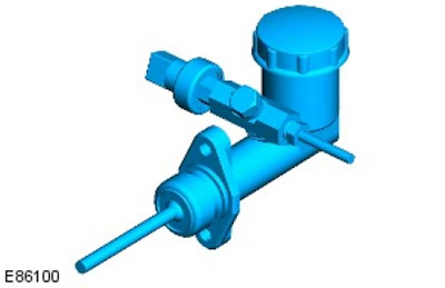
The clutch pedal position sensor is located on the clutch master cylinder. The clutch pedal position sensor is a pressure measuring sensor. When the clutch pedal is depressed, the clutch pedal position sensor sends a signal to the ECM, which reduces engine torque.
Generator
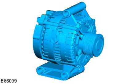
The generator has a multifunctional charging voltage regulator (14 V) with 6-12 zener diode bridge rectifiers.
The ECM monitors the load on the electrical equipment through a PWM signal and adjusts the generator power in accordance with consumer requests. The ECM also monitors the battery temperature to determine the charge control setpoint for the battery. This parameter is needed to protect the battery from damage. At low battery temperatures, its ability to accept charging is extremely low, and to compensate for this circumstance, it is necessary to increase the charging voltage as much as possible, however, at high temperatures, the charging voltage must be reduced to prevent excessive gas formation and, as a result, loss of water from the electrolyte.
The generator circuit contains intelligent controls that reduce the load on the generator if there is a need to maximize the use of engine torque for other purposes. For such control, three signals from those coming to the ECM are used:
- Generator sensor (sensor A) measures the voltage in the CJB.
- Generator status sensor (Alt Com) sends the desired generator output voltage value from the ECM to the generator.
- Generator status sensor (Alt Mon) Sends to the ECM the amount of current in the generator load circuit. This signal notifies the ECM of a malfunction, which then sends a message to the instrument cluster via the CAN bus to turn on the charging indicator lamp.
Control scheme
NOTE: A = wired; D = high speed CAN bus
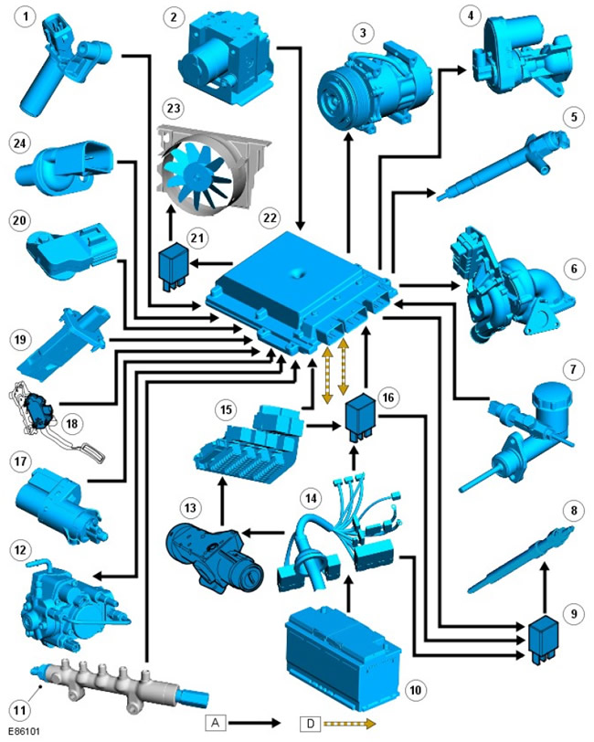
| Pos. | spare part no | Name |
| 1 | - | CKP |
| 2 | - | Anti-lock brake control unit (ABS) |
| 3 | - | Air conditioning compressor |
| 4 | - | EGR Exhaust Gas Recirculation valve |
| 5 | - | injectors |
| 6 | - | Turbocharger (turbocharging) |
| 7 | - | Clutch position sensor |
| 8 | - | glow plugs |
| 9 | - | Glow plug relay |
| 10 | - | Accumulator battery |
| 11 | - | Fuel rail pressure sensor |
| 12 | - | Fuel pump |
| 13 | - | ignition switch |
| 14 | - | BJB |
| 15 | - | CJB |
| 16 | - | Glow plug relay |
| 17 | - | Brake pedal sensor |
| 18 | - | APP |
| 19 | - | MAF/IAT sensor |
| 20 | - | MAP sensor |
| 21 | - | Electric fan relay |
| 22 | - | The engine control unit |
| 23 | - | Engine cooling system fan |
| 24 | - | CMP sensor |
Comments on this article