car logo Ford
car logo Volkswagen
car logo BMW
car logo Opel
car logo Audi
car logo Toyota
car logo Peugeot
English Русский
Български
Беларускі
Український
Српски
Hrvatski
Română
Polski
Slovenský
Magyar


Main
Freelander
Discovery
Range Rover
Defender
Contacts
Articles

Calculating the distance to obstacles (Discovery 3)

 
  • Main
  • Discovery
  • Discovery 3
  • Electrical equipment
  • Instruments and control lamps
  • Calculating the distance to obstacles
 
        0  
Contents: Operation of sensors ⇩ Detection Zone ⇩ Detecting an obstacle and…⇩
On vehicles equipped with rear sensors only, the parking assistance system is automatically activated when the ignition key is in position II and reverse gear is engaged. The parking assistance system control module only activates the system if reverse gear is engaged for at least 1 second. This avoids annoying audible warnings when moving the selector lever between positions D and P on vehicles with a manual transmission.

When the rear parking assist system is activated, the system control module turns on the LED indicator in the switch button, turns on the sensors and issues a command to emit a single sound signal confirming the activation of the system. If an object appears within the sensor's range, then with the system on, a sequence of warning sounds is immediately emitted.

If the parking assistance system is not required, it can be temporarily deactivated by pressing the switch. For vehicles with rear sensors only, the system can be reactivated by pressing the switch again or by turning the ignition off and on again. The system will then be automatically activated when reverse gear is selected. The system remains active when shifting from reverse to neutral. This takes into account the likelihood that the driver will continue (in any way) move the car backwards with the gearbox in neutral.

When a trailer is connected, the parking assistance module receives a signal via the CAN bus from the central electrical distribution box. Upon receiving this signal, the parking assistance control module suspends the system.


On vehicles equipped with front and rear sensors, the parking assistance system is automatically activated when the ignition is turned on. (position II), the selector lever is not in the Park position and the electronic parking brake is released. At speeds above 10 km/h, the front parking aid is deactivated. When the speed drops to 6 km/h, the front parking aid is resumed. If the electronic parking brake (EPB) is applied or the selector lever is moved to the Park position, the parking aid is deactivated.

Operation of sensors


The parking assistance module analyzes the data received from the sensors to detect obstacles in the sensor's field of view. If no obstacles are detected, the parking assistance system does not emit any audible signals. If an obstacle is detected, the parking assistance speaker emits a series of audible signals.

The maximum obstacle detection distance is 1800 mm. When an obstacle is detected, the interval between the sound signals decreases as you approach it, and at a distance of approximately 350 mm from the obstacle the sound signal becomes continuous.

If, from the moment an obstacle is detected, the distance between the obstacle and the central sensors does not decrease further, the interval between the sound signals does not change. If an object is detected by only one extreme sensor, the warning signal will stop after 5 seconds, unless the distance from the object to the extreme sensor changes.

Detection Zone
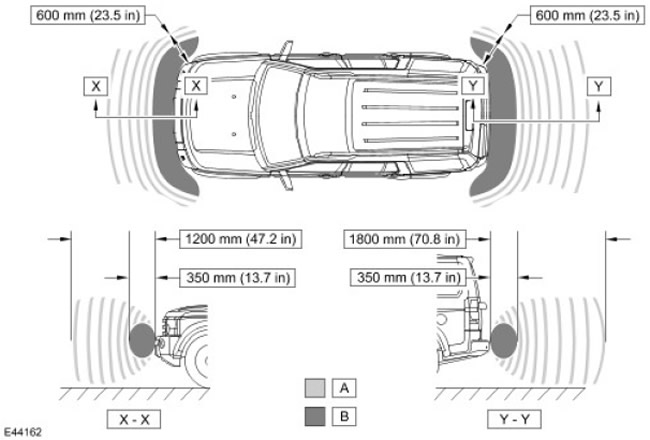

Detection Zone


Item nameSpare part catalog numberDescription
A-Intermittent warning sound
B-Continuous warning sound


Detecting an obstacle and calculating the distance to it


When operating in a combined transmit/receive mode, the sensor emits ultrasonic pulses and receives signals reflected from an obstacle. The parking assistance control module amplifies the reflected signals and compares them with the threshold values programmed in the program to calculate the distance. This is achieved by determining the time elapsed between the transmission and reception of the ultrasonic signal.

When the sensor operates in the receiving mode, it receives the radiation signals of the neighboring sensor. This mode is used to improve the accuracy of the system.

The obstacle detection cycle consists of transmitting and receiving a series of pulses by one sensor operating in combined mode on commands from the parking assistance control module. The computer then switches this and the adjacent sensors to the mode of receiving only the reflected signal. After a short pause, the operation is repeated, but now the next sensor operates in combined mode. The cycle continues until all 4 sensors emit ultrasonic signals. This takes about 100 milliseconds. The control module performs several measurements of the signals of the same sensor to eliminate random errors in the calculations.

If the object is located directly opposite the sensor, the distance is calculated based on the time between the transmission and reception of the signal. If the obstacle is located between two sensors, the control module calculates the distance based on the signals from the two sensors, solving the triangulation problem.


To solve the triangulation problem, the control module must know the distance between the individual sensors in the bumper. This information is stored in the control module's memory. Knowing the distances from each sensor to the obstacle and the distance between adjacent sensors, the control module can calculate the minimum distance from the car's bumper to the obstacle.

When the car approaches several obstacles at the same time, the control module determines the distance to the nearest one.


This article is available at russian, bulgarian, belarusian, ukrainian, serbian, croatian, romanian, polish, slovak, hungarian
Article review: Saveliy Ushakov


Previous articles
The structure and description of the instrument panel
Instrument cluster warning lights
Analog instrument cluster instruments
Diagnostics and testing of the instrument panel
Removal and installation the instrument panel
The device and description of the sound signal
Information and Message Center
Information display

Current article
Calculating the distance to obstacles

Next articles
Parking assistance diagnostics and testing
Parking assistance speaker
Rear interior parking assistance sensor
Rear exterior parking assistance sensor
Parking assistance system module
Front interior parking assistance sensor
Front exterior parking assistance sensor


Similar articles from Land Rover repair manuals:
• Distance between points of the front and side parts of the body Freelander 1 (1997-2006)

Comments on this article


No comments yet


How much will 21 + 28 =


Discovery 3 
  • General information
  • Using the manual
  • Precautionary measures
  • Service Information
  • Technique
  • Health protection
  • Road test
  • Identification codes
  • Jacking and lifting
  • Maintenance - diesel
  • Maintenance - petrol
  • Chassis
  • Suspension
  • Front suspension
  • Rear suspension
  • Wheels and tires
  • Dynamic suspension
  • Cardan shaft
  • Rear drive axle
  • Front drive axle
  • Front axle axles
  • Rear axle axles
  • Brake system
  • Parking brake
  • Hydraulic brake
  • Vacuum brake booster
  • Anti-lock braking system
  • Steering
  • Steering column
  • Power unit
  • Petrol engine 4.0L
  • Petrol engine 4.4L
  • Diesel engine 2.7L
  • Engine cooling
  • Fuel supply
  • Drive units
  • Launch system
  • Ignition system
  • Emission reduction
  • Air filtration
  • Fuel vapor control
  • Electronic control part
  • Car gearbox
  • Clutch
  • All-wheel drive systems
  • Transfer case
  • Exhaust system
  • Fuel tank and lines
  • Acceleration control
  • Electrical equipment
  • Climate control
  • Instruments and control lamps
  • Battery and charging system
  • Information system
  • Lighting and headlights
  • Power distribution
  • Electronic Function Group
  • Body and coating
  • Body elements
  • Interior and body trim
  • Mirrors and glasses
  • Seats
  • Instrument panel and console
  • Handles and locks
  • Windshield wipers and washers
  • Sunroof and bumpers
  • Safety system
  • Body repairs
  • Repair of front end elements
  • Repair of back elements
  • Side panel repair
  • Frame and body mount

Discovery 1 
  • General information
  • Technical specifications
  • Introduction to manual
  • Troubleshooting
  • Power unit
  • Diesel engine Tdi
  • Petrol engine V8i (3.9 l)
  • Petrol engine V8i (4.0 l)
  • Petrol engine Mpi
  • Reducing harmful emissions
  • Fuel system Tdi
  • Fuel system MFi
  • Fuel system SFi
  • Fuel system MPi (MEMS)
  • Cruise control
  • Cooling system (Tdi)
  • Cooling system (V8i)
  • Cooling system (MPi)
  • Exhaust system
  • Transmission
  • Clutch
  • Manual gearbox R380
  • Manual gearbox LT 77
  • Transfer case LT230T
  • Automatic gearbox
  • Cardan shaft
  • Rear axle
  • Front axle
  • Chassis
  • Steering system
  • Front suspension
  • Rear suspension
  • Brake system
  • Wheels and tires
  • Body and interior
  • Passive safety
  • Doors, locks and windows
  • Exterior body parts
  • Interior trim details
  • Seats
  • Electrical equipment
  • Heating and ventilation
  • Air conditioning
  • Windscreen wipers
  • Starting and charging system
  • Equipment and devices
  • Lighting and headlights


LRman.ru © 2013-2026 | Mobile version | Free Lander | Discovery | Range Rover | Defender | Contacts | | Sitemap |
Car repair and service instructions Land Rover: Freelander, Discovery, Range Rover, Defender
We use cookies to make pages load faster and provide a more user-friendly experience 🍪