Contents: Control lamps ⇩ Functional purpose of control lamps ⇩ 1. Air suspension indicator light ⇩ 2. Transfer case low range indicator…⇩ 3. Hill Descent Control (HDC)…⇩ 4. Dynamic Stability Control…⇩ 5. Ignition/no charge indicator light ⇩ 6. Low oil pressure warning light ⇩ 7. Glow plug indicator light (for…⇩ 8. Malfunction Indicator Lamp (MIL) ⇩ 9. Supplemental Restraint System…⇩ 10 and 11. Left and right turn…⇩ 12. High beam indicator lamp ⇩ 13. Tire Pressure Monitoring System…⇩ 14. Seat belt indicator light ⇩ 15 and 38. Brake system indicator…⇩ 16. Anti-lock brake system (ABS)…⇩ 17. Cruise control system indicator…⇩ 18. Adaptive Front Lighting System…⇩ 19 and 36. Parking brake malfunction…⇩ 20 and 37. Parking brake indicator…⇩ 21. Front fog light indicator lamp ⇩ 22. Rear fog light indicator lamp ⇩ 23. Trailer indicator light ⇩ 24. Auxiliary heater indicator lamp ⇩ 25. Engine Management System (EMS)…⇩ 26. Transmission Malfunction…⇩ 27. Hill Descent Control (HDC)…⇩ 28. Water in fuel indicator light ⇩ 29. Transmission Overheating Warning…⇩ 30. Windscreen washer fluid low…⇩ 31. Door incomplete closing…⇩ 32. Parking brake city mode…⇩ 33. Low tire pressure warning light ⇩ 34. Low coolant level indicator lamp ⇩ 35. Speed limit indicator light ⇩ 39. Adaptive Cruise Control (ACC)…⇩
Control lamps
The control lamps are located in different parts of the instrument panel. The control lamps can be divided into two groups: self-controlled and externally controlled.
The activation of the self-controlling indicator lamps depends on the software logic of the instrument cluster.
The instrument cluster software controls the activation of the indicator lights when the ignition is turned on, as well as any indicator lights that are controlled by the instrument cluster, such as the low fuel indicator light.
Power for externally controlled indicator lamps is supplied from a control module of another system or is switched on by the instrument panel upon receipt of a message via the bus from a module of another subsystem.
Some indicator lamps are activated by the external subsystem module, but the instrument cluster control logic is used. These indicator lamps are listed in the following table, indicating the type of control.
The table also indicates the available indicator lamps and which of the indicator lamps are switched on when the ignition is turned on and the type of control. (external or internal).
| Control lamp | Glow color | Checking the lamps | Self-government (S) / External management (E) |
| Ignition/no charging | Red | No | E |
| Low oil pressure | Red | No | E |
| Glow plugs are on | Orange | * No (turns on when the ignition is turned on, confirming that the glow plugs are on) | E |
| MIL | Orange | * Yes | E |
| Seat belts | Red | No | E |
| SRS | Red | * Yes | E |
| Adaptive cruise control system (if any) | Orange | No | E |
| Transfer case low range | Green | No | E |
| Air suspension | Orange/ red | Да | E |
| HDC enabled | Green | No | E |
| HDC system malfunction | Orange | Да | E |
| DSC/traction control system | Orange | Да | E |
| Left turn signal | Green | No | E |
| Right turn signal | Green | No | E |
| Trailer | Green | No | E |
| High coolant temperature | Red | Да | S |
| High beam | Blue | No | E |
| ABS malfunction | Orange | * Yes | E |
| Low fuel level | Orange | Да | S |
| Cruise control system | Orange | No | E |
| City parking brake mode | It doesn't work | - | - |
| Parking brake malfunction | Orange | Да | E |
| Parking brake engaged warning | Red | No | E |
| Front fog lights | Green | No | E |
| Rear fog lights | Orange | No | E |
| Signaling | Red | No | E |
| EMS system malfunction | Orange | Да | E |
| Transmission failure | Orange/ red | Да | E |
| Transmission overheating | Orange | Да | E |
| Windshield washer fluid level low | Orange | Да | E |
| Doors not closing completely | Red | No | E |
| Auxiliary heater (does not work - only lamp check) | Red | Да | E |
| Tire pressure monitoring | Orange | Да | E |
| Low coolant level. | Orange | No | E |
| Speeding | Orange | No | E |
| Presence of water in fuel | It doesn't work | - | - |
| Low Tire Pressure Warning | Orange | Да | E |
| Brake system malfunction warning | Orange / red | Да | E |
| Adaptive front lighting system | Orange | Да | E |
* lamp check is performed by the subsystem module, not by the instrument panel
Functional purpose of control lamps
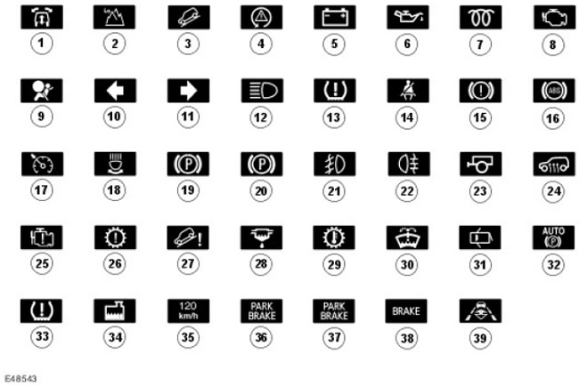
| Item name | Spare part catalog number | Description |
| 1 | - | Air suspension |
| 2 | - | Transfer case low range |
| 3 | - | HDC enabled |
| 4 | - | DSC/traction control system |
| 5 | - | Ignition/no charging |
| 6 | - | Low oil pressure |
| 7 | - | Glow plugs are on (for diesel engine models only) |
| 8 | - | Malfunction indicator lamp (for petrol engine models only) |
| 9 | - | SRS Malfunction Warning |
| 10 | - | Left turn signal indicator lamp |
| 11 | - | Right turn signal indicator lamp |
| 12 | - | High beam |
| 13 | - | Tire pressure monitoring system |
| 14 | - | Warning about loose bent seat belts |
| 15 | - | Brake system malfunction warning |
| 16 | - | ABS |
| 17 | - | Cruise control system |
| 18 | - | Adaptive front lighting system |
| 19 | - | Parking brake malfunction (except North American countries) |
| 20 | - | Parking brake engaged warning (except North American countries) |
| 21 | - | Front fog lights |
| 22 | - | Rear fog lights |
| 23 | - | Trailer |
| 24 | - | Auxiliary heater indicator lamp (does not work - only lamp check) |
| 25 | - | Engine management system malfunction |
| 26 | - | Transmission failure |
| 27 | - | HDC system malfunction |
| 28 | - | Presence of water in fuel (does not work) |
| 29 | - | Transmission overheating |
| 30 | - | Windshield washer fluid level low |
| 31 | - | Doors not closing completely |
| 32 | - | City parking brake mode (does not work) |
| 33 | - | Low Tire Pressure Warning |
| 34 | - | Low coolant level |
| 35 | - | Speed limit warning (for Gulf countries only) |
| 36 | - | Parking brake malfunction (for North American countries only) |
| 37 | - | Parking brake engaged warning (for North American countries only) |
| 38 | - | Brake system malfunction warning (for North American countries only) |
| 39 | - | Adaptive Cruise Control (ACC) (if any) |
The following is a discussion of the functionality of each indicator lamp listed above. Some indicator lamps are accompanied by an audible signal from the instrument cluster buzzer and a corresponding message on the message center display in high-end instrument clusters. Some indicator lamps are only available in standard instrument clusters, while in high-end instrument clusters the indicator lamps are replaced by messages.
1. Air suspension indicator light
The air suspension indicator lamp is controlled by the instrument cluster software when it receives a signal on the CAN bus from the air suspension control module. The air suspension control module transmits a number of different signals about the operation of the air suspension system. The instrument cluster interprets these signals and, depending on these signals, lights the indicator lamp orange or red. To warn the driver, some signals are accompanied by a request for an audible signal from the instrument cluster buzzer.
2. Transfer case low range indicator light
The transfer case low range indicator lamp is controlled by the instrument cluster software when receiving CAN bus signals from the transfer case control module. During the shift from high to low range, the indicator lamp flashes green. Once the shift is complete, the low range indicator lamp remains illuminated until high range is selected.
In addition, the transfer case control module sends a request to the instrument cluster to emit a single chirp to notify the driver that the selected range has been shifted. On higher-end instrument clusters, range shift information is also displayed in the message center display.
3. Hill Descent Control (HDC) indicator light
The HDC indicator lamp is controlled by the instrument cluster software when it receives CAN bus signals from the ABS module. The indicator lamp lights up green when the HDC system is on and the vehicle speed is below a preset threshold. If the vehicle speed exceeds the preset threshold, the indicator lamp flashes until the vehicle speed is reduced. In high-end instrument clusters, a message is displayed in the message center. For more information, refer to AntiLock Control - Traction Control (206-09A Anti-Lock Control - Traction Control)
If the brake disc temperature exceeds a preset value as a result of HDC operation, HDC begins to reduce braking efficiency. The HDC indicator lamp flashes during the reduction in braking efficiency and a corresponding message is displayed in the message center display on high-end instrument clusters. Once the discs have cooled to an acceptable temperature, HDC is reactivated and the HDC indicator lamp remains lit.
4. Dynamic Stability Control (DSC)/Traction Control Indicator Lamp
The DSC/traction control indicator lamp is controlled by the instrument cluster software when receiving CAN bus signals from the ABS module. During the lamp check, the indicator lamp lights orange for 3 seconds when the ignition is switched on. If no faults are found, the indicator lamp goes out when the lamp check is completed.
When the DSC system is switched on, the indicator lamp flashes to notify the driver that the system is regulating engine output and braking force. If the indicator lamp remains illuminated after the bulb check or while driving, the DSC system is faulty or has been switched off by the driver using the DSC switch on the instrument panel.
5. Ignition/no charge indicator light
The ignition/no charge indicator lamp is controlled by the instrument cluster software when receiving CAN bus signals from the engine control module (ECM). The indicator lamp illuminates red when the ignition key is in position II and goes out after the engine has started.
If the indicator light remains on after the engine is started or stays on while the vehicle is moving, this means the alternator is faulty.
6. Low oil pressure warning light
The low oil pressure indicator lamp is directly connected by wires to the instrument cluster. The indicator lamp lights up red when the ignition key is in position II. After the engine has started or the oil pressure has increased, the indicator lamp should go out. If the indicator lamp remains on after the engine has started or lights up while the vehicle is moving, the vehicle should be stopped as soon as possible and the engine should be switched off and not started until the fault has been corrected.
7. Glow plug indicator light (for diesel engine models only)
The glow plug indicator lamp is controlled by the instrument cluster software when it receives a signal via the CAN bus from the engine control module (ECM). The indicator lamp is located in the same place in the instrument cluster as the MIL indicator lamp in gasoline models. When the ignition key is turned to position II, the indicator lamp illuminates in orange. The duration of the indicator lamp illumination depends on the engine temperature, and in some cases, at high engine temperatures, it does not illuminate at all. The illumination of the indicator lamp depends on signals transmitted by the ECM via the CAN bus, the duration of which is determined by the duration of power supplied to the glow plugs to warm up the combustion chambers. For more information, refer to Glow Plug System (303-07C Glow Plug System)
Once the glow plugs have finished heating up, the indicator lamp goes out, informing the driver that the engine can be started.
8. Malfunction Indicator Lamp (MIL)
The MIL indicator lamp is controlled by the instrument cluster software upon receipt of CAN bus signals from the ECM. The indicator lamp is illuminated by the lamp check performed by the ECM when the ignition switch is turned to position II. The indicator lamp goes out after the engine is started.
If the MIL remains on after the engine has been started or remains on while the vehicle is being driven, there is a fault in the system that should be corrected as soon as possible. When the MIL comes on, there is a fault with the on-board diagnostics (OBD) system that is causing emissions to increase. This could be due to a fault in the engine management system or transmission.
9. Supplemental Restraint System (SRS) Warning Light
The SRS indicator lamp is controlled by the supplemental restraint system module, which sends signals to the instrument cluster via the CAN bus. The indicator lamp illuminates for 6 seconds during the lamp check performed by the supplemental restraint system control module when the ignition key is turned to position II. If a malfunction is detected in the SRS system, the supplemental restraint system control module illuminates the indicator lamp in red until the malfunction is corrected.
The instrument cluster also checks the functionality of the indicator lamp LED. To notify the driver of a malfunction of the indicator lamp LED, the message "5R5" (SRS) is displayed on the trip meter display.
10 and 11. Left and right turn signal indicator lamps
The direction indicator lamps are controlled by the instrument cluster software when receiving signals from the central junction box (CJB) via the medium speed CAN bus. When a direction indicator is switched on, the CJB sends a command to the instrument cluster to switch on the corresponding direction indicator lamp. The instrument cluster software controls the flashing rate of the green indicator lamp. If the direction indicators are working properly, the indicator lamps flash slowly and an audible signal is emitted by the instrument cluster annunciator. If there is a fault in the system, the instrument cluster doubles the flashing rate of the indicator lamps when receiving a message from the CJB.
The hazard warning lamps are also controlled by the CJB and instrument cluster software and operate in the same way as the direction indicator lamps. The hazard warning lamps can operate with the ignition off, so a signal from the CJB to the instrument cluster via the CAN bus that turns on both direction indicator lamps also wakes the instrument cluster from standby mode.
12. High beam indicator lamp
The high beam indicator lamp is controlled by the instrument cluster software when receiving signals from the central junction box (CJB) via the medium speed CAN bus. When the high beam switch is moved to the high beam or high beam flash position, the CJB sends a message to the instrument cluster via the CAN bus to illuminate the high beam indicator lamp in blue.
13. Tire Pressure Monitoring System (TPMS) Warning Light:
The Tire Pressure Monitoring System (TPMS) indicator light is controlled by the instrument cluster software when it receives CAN bus signals from the TPMS module. The indicator light illuminates orange for 3 seconds during the bulb check performed by the TPMS module when the ignition key is turned to position II. If the indicator light remains illuminated after the engine is started or illuminates while the vehicle is being driven, the TPMS module has detected a malfunction. The tire pressure must be checked manually until the malfunction is corrected.
14. Seat belt indicator light
The seat belt indicator lamp is controlled by the supplemental restraint system control module and instrument cluster software upon receipt of CAN bus signals from the supplemental restraint system control module.
The indicator lamp lights red when the ignition key is in position II. The indicator lamp remains lit until the seat belt is fastened. If the seat belt of the occupied front seat is not fastened and the vehicle speed exceeds 8 km/h, the indicator lamp flashes and the instrument cluster buzzer sounds intermittently for 10 seconds. This warning is repeated every 30 seconds until the seat belt is fastened, the vehicle speed decreases to less than 5 km/h, or the ignition is switched off.
On North American vehicles, the indicator light remains on until the seat belt is fastened, the vehicle speed is reduced to less than 5 km/h (3 mph), or the ignition is turned off.
15 and 38. Brake system indicator lamp
This indicator lamp is controlled by signals coming from the ABS module via the CAN bus and indicates malfunctions of the Emergency Brake Assist (EBA) or Electronic Brakeforce Distribution (EBD) system. Brake pad wear and brake fluid level monitoring is performed by the instrument cluster, which is wired to the brake pad wear and brake fluid level sensors.
Depending on the nature of the fault, the indicator lamp lights up yellow or red. The indicator lamp lights up when the lamps are checked when the ignition is turned on. The indicator lamp lights up orange for 1.5 seconds and red for another 1.5 seconds. If no faults are found, the indicator lamp goes out after the lamp check is complete.
Each function of the brake warning lamp is assigned a priority. Faults that require the lamp to light red have a higher priority than faults that require the lamp to light orange.
Brake pad wear
The front left inner pad and the rear right inner pad are equipped with wear sensors. The pad wear sensors are connected in series with the instrument cluster, which constantly monitors these circuits. When one or both pads reach the permissible wear limit (approximately 75%), the pad wear sensor circuit is interrupted and this is detected by the instrument cluster software. The instrument cluster lights the brake system warning lamp in red and, on high-end instrument clusters, the message center display shows the message "CHECK BRAKE PADS" (check the brake pads). After replacing the pads, the instrument panel detects a short circuit and cancels the indicator lamp and the display of the message. (if applicable) when turning the ignition key to position II.
EBA/EBD system malfunction warning
If a fault occurs in the EBA or EBD systems, the ABS module transmits a signal via the CAN bus to the instrument cluster. The instrument cluster software switches on the brake system indicator lamp in orange for minor faults in the eBa/EBD systems or in red for serious faults in these systems. The indicator lamp remains lit until the fault is rectified.
Low brake fluid level
A sensor is installed in the brake fluid reservoir, which is directly connected to the instrument cluster. When the ignition key is turned to position II, the fluid level is checked. In order to avoid false warnings while the vehicle is moving, the sensor is checked every 25 seconds. If the brake fluid level is insufficient, the instrument cluster turns on the brake system warning light in red, and in instrument clusters with improved equipment, the message center display shows the message "CHECK BRAKE FLUID" (check the brake fluid level). The low brake fluid level indicator lamp comes on and is accompanied by a sound signal from the instrument cluster buzzer.
16. Anti-lock brake system (ABS) indicator light
The ABS indicator lamp is controlled by the ABS module, which transmits signals to the instrument cluster via the CAN bus. The indicator lamp lights orange for 3 seconds during the lamp check performed by the ABS module when the ignition key is turned to position II. If the indicator lamp remains lit after the engine has been started or lights while the vehicle is being driven, this indicates that there is a malfunction in the ABS system and the system functions cannot be performed.
If during the bulb check the indicator comes on for 0.5 seconds, goes off for 0.5 seconds, and then stays on for the remaining two seconds of the bulb check mode, this indicates that there is a fault stored in the ABS module memory.
If the warning lamp comes on due to a sensor malfunction, it will remain on the next time the ignition is turned on even after the malfunction has been corrected. The warning lamp will go out when the vehicle speed exceeds 20 km/h. This allows the ABS module to perform a thorough system check and verify the validity of the output signals from the replaced sensor.
17. Cruise control system indicator light
The cruise control indicator lamp is controlled by the ECM and instrument cluster software upon receipt of CAN bus signals from the ECM. The indicator lamp illuminates when the cruise control system is resumed and the current speed is within 8 km/h of the set speed, or when the cruise control system is engaged and the current speed is maintained within 8 km/h of the set speed.
18. Adaptive Front Lighting System (AFS) indicator lamp
The AFS indicator lamp is controlled by the AFS control module and the instrument cluster software when receiving CAN bus signals from the AFS control module. The indicator lamp illuminates orange for 3 seconds during the bulb check when the ignition key is turned to position II.
The AFS indicator lamp is designed to inform the driver of malfunctions in the AFS system. If a malfunction occurs, the indicator lamp remains continuously lit until the malfunction is corrected.
19 and 36. Parking brake malfunction indicator lamp
The parking brake malfunction indicator lamp is controlled by the instrument cluster software upon receipt of CAN bus signals from the Electronic Parking Brake (EPB) control module. The indicator lamp illuminates orange for 3 seconds during the bulb check when the ignition key is turned to position II. If a malfunction is detected in the EPB system, the EPB control module requests illumination of the indicator lamp, which remains illuminated until the malfunction is corrected.
20 and 37. Parking brake indicator lamp
The parking brake indicator lamp is controlled by the instrument cluster software when receiving CAN bus signals from the electronic parking brake (EPB) control module. The indicator lamp lights red when the parking brake is applied. When the ignition is turned off, the indicator lamp remains lit for 3 minutes. If a malfunction occurs that prevents the parking brake from being applied, this indicator lamp flashes and the parking brake malfunction indicator lamp lights.
21. Front fog light indicator lamp
The front fog lamp indicator lamp is controlled by the CJB, which switches the indicator lamp on via a hardwired connection to the instrument cluster. The indicator lamp glows green continuously when the front fog lamps are on and the ignition key is in position II.
22. Rear fog light indicator lamp
The rear fog lamp indicator lamp is controlled by the CJB, which switches the indicator lamp on via a hardwired connection to the instrument cluster. The indicator lamp glows continuously in orange when the rear fog lamps are on and the ignition key is in position II.
23. Trailer indicator light
The trailer indicator lamp is controlled by the instrument cluster software when receiving signals from the Central Junction Box (CJB) via the medium speed CAN bus. If the trailer wiring is connected to the vehicle electrical system, the CJB sends a signal to the instrument cluster to turn on the trailer indicator lamp when the direction indicator switch is operated. The instrument cluster software controls the flashing rate of the green indicator lamp. The slow flashing of the trailer indicator lamp is accompanied by the instrument cluster buzzer sounds at the same rate as the direction indicator lamps.
24. Auxiliary heater indicator lamp
The auxiliary heater indicator lamp lights for 3 seconds during the bulb check when the ignition key is turned to position II. u788.2
25. Engine Management System (EMS) Malfunction Indicator Lamp
The EMS malfunction indicator lamp is only provided in standard instrument clusters. The indicator lamp is controlled by the ECM and instrument cluster software when receiving CAN bus signals from the ECM. The indicator lamp lights up in orange during the bulb check when the ignition key is turned to position II. The indicator lamp goes out after the engine is started. The EMS malfunction indicator lamp lights up continuously when there are malfunctions in the engine management system that do not affect the operation of the exhaust system. The indicator lamp goes out only when the malfunction is corrected.
The EMS malfunction indicator lamp also informs the driver about a reduction in engine performance or a switch to emergency operation mode.
26. Transmission Malfunction Indicator Lamp
The transmission malfunction indicator lamp is controlled by the transfer case control module, rear differential control module, powertrain control module and instrument cluster software. The indicator lamp is illuminated by the instrument cluster when it receives a signal on the CAN bus from one of these control modules. The instrument cluster interprets these signals and illuminates the indicator lamp in orange or red depending on the malfunctions associated with the transfer case, rear differential or automatic transmission. An orange indicator lamp indicates minor malfunctions that should be corrected at any opportunity. A red indicator lamp indicates major malfunctions that should be corrected at the earliest opportunity.
27. Hill Descent Control (HDC) Malfunction Indicator Lamp
The HDC malfunction indicator lamp is only provided in standard instrument clusters. In high-end instrument clusters, malfunction information is displayed in the message center display as messages. The HDC malfunction indicator lamp is controlled by the instrument cluster software when it receives CAN bus signals from the ABS module. The indicator lamp lights up in orange when there is a malfunction in the HDC system. The indicator lamp lights up in orange for 3 seconds during the bulb check when the ignition key is turned to position II. If a malfunction is detected in the HDC system, the indicator lamp lights up in orange. For more information, refer to Anti-Lock Control -Traction Control (206-09A Anti-Lock Control - Traction Control)
If during the bulb check the indicator comes on for 0.5 seconds, goes off for 0.5 seconds, and then stays on for the remaining two seconds of the bulb check mode, this indicates that there is a fault stored in the ABS module memory.
If the warning lamp comes on due to a sensor malfunction, it will remain on the next time the ignition is turned on even after the malfunction has been corrected. The warning lamp will go out when the vehicle speed exceeds 20 km/h. This allows the ABS module to perform a thorough system check and verify the validity of the output signals from the replaced sensor.
If the brake disc temperature exceeds a preset value as a result of HDC operation, HDC begins to reduce braking efficiency. The HDC malfunction indicator lamp flashes while braking efficiency is reduced. Once the disc temperature has cooled to an acceptable level, HDC is activated again and the HDC malfunction indicator lamp goes out.
28. Water in fuel indicator light
This indicator light does not work.
29. Transmission Overheating Warning Light
The transmission overheat indicator lamp is controlled by the instrument cluster software upon receipt of CAN bus signals from the transfer case control module, rear differential control module, and automatic transmission control module. The indicator lamp illuminates orange for 3 seconds during the bulb check when the ignition key is turned to position II. If one or more control modules determines that the temperature of the component it controls has reached the overheat threshold, the appropriate control module transmits a CAN bus signal to the instrument cluster, which illuminates the indicator lamp for the duration of the overheat condition.
30. Windscreen washer fluid low level indicator light
The low windshield washer fluid level indicator lamp is only provided in standard instrument clusters. In upgraded instrument clusters, low fluid level information is displayed in the message center display as appropriate messages. The low windshield washer fluid level indicator lamp is controlled by the instrument cluster. The windshield washer fluid level sensor is directly wired to the instrument cluster, which monitors the sensor output signals. The indicator lamp lights up orange for 3 seconds when the ignition key is turned to position II. If the fluid level in the windshield washer reservoir drops to a preset level, the instrument cluster receives the sensor signals, turns on the indicator lamp and emits a single beep to notify the driver. To prevent erroneous warnings due to fluid movement in the reservoir, the instrument cluster monitors the level sensor output signals every 15 seconds. The indicator lamp goes out when the reservoir is refilled.
31. Door incomplete closing indicator light
The door ajar indicator lamp is controlled by the instrument cluster software when receiving CAN bus signals from the central junction box (CJB). The indicator lamp illuminates red if one of the front or rear doors, the bonnet or the tailgate is open when the ignition key is in position II.
32. Parking brake city mode indicator lamp
This indicator light does not work.
33. Low tire pressure warning light
The low tire pressure warning lamp is only provided in standard instrument clusters. In high-grade instrument clusters, the corresponding warning messages are displayed in the message center display. The tire pressure monitoring system (TPMS) warning lamp is controlled by the instrument cluster software upon receipt of CAN bus signals from the TPMS module. The lamp illuminates red for 3 seconds during the TPMS module bulb check when the ignition key is turned to position II.
If the warning light remains on after the engine has been started or remains on while the vehicle is moving, stop the vehicle as soon as possible and check the tire pressure.
34. Low coolant level indicator lamp
The low coolant level indicator lamp is controlled by the instrument cluster. The coolant level sensor has a direct wire connection to the instrument cluster, which monitors the output signals of the sensor. The indicator lamp lights orange for 3 seconds when the ignition key is turned to position II. If the coolant level in the expansion tank drops to a preset level, the instrument cluster receives corresponding signals from the low coolant level sensor. The instrument cluster turns on the indicator lamp in flashing mode for 5 seconds, accompanied by an audible signal, after which the lamp lights continuously. The indicator lamp remains lit until coolant is added to the required level. To prevent erroneous warnings due to fluid movement in the tank, the instrument cluster monitors the output signals of the level sensor every 15 seconds.
35. Speed limit indicator light
The overspeed warning lamp is only provided in standard instrument clusters. In upgraded instrument clusters, information about the overspeed limit is displayed in the message center display as appropriate messages. The overspeed warning lamp is controlled by the instrument cluster and the speed threshold is set in the default settings. The instrument cluster receives vehicle speed data from the ABS module via the CAN bus. The instrument cluster software monitors the speed signals and determines whether the threshold value is exceeded. When the threshold value is exceeded, the warning lamp lights continuously as long as the overspeed condition exists.
39. Adaptive Cruise Control (ACC) indicator light (if any)
The ACC indicator light is controlled by the ACC module and the instrument cluster software. The indicator light comes on when the cruise control system is engaged and the radar system detects another vehicle ahead. The indicator light turns orange to notify the driver that the ACC system is engaged and is automatically adjusting the vehicle speed to maintain a set distance from the vehicle in front.
Comments on this article