Special tool
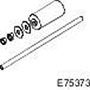 204-598 Hydraulic Cylinder 10t 204-598 Hydraulic Cylinder 10t | 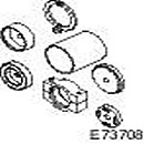 204-598-01 Remover/Installer, Subframe Bushing Gu 204-598-01 Remover/Installer, Subframe Bushing Gu |
NOTE: The removal procedure descriptions in this manual may contain installation steps.
1. Raise and support the vehicle.
WARNING: Ensure that the vehicle is supported securely.
2. Remove both rear wheels. Refer to procedure: Wheel and Tire (204-04 Wheels and Tires, Removal and Installation).
3. Remove the rear subframe assembly to gain access. Refer to procedure: Rear Subframe (502-00 Uni-Body, Subframe and Mounting System, Removal and Installation).
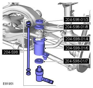
4. Remove the bushing. Special tool: 204-598-01
Mark the position of the elements to facilitate subsequent installation.
Special tool 204-598-01/8 is used to begin the bushing removal process and should be removed once the bushing is free as it will not fit through the subframe bushing bore.
Installation
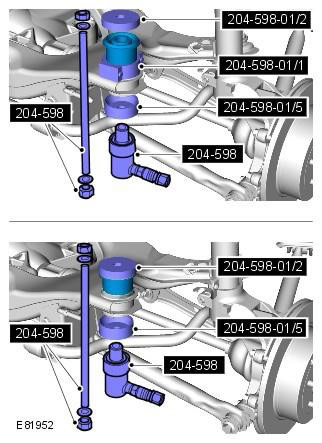
1. Install the bushing. Special tool: 204-598, 204-598-01
Make sure the correct special tool is used to set the bushings to the correct depth.
The alignment marks must be centered.
2. Install the rear subframe assembly. Refer to procedure: Rear Subframe (502-00 Uni-Body, Subframe and Mounting System, Removal and Installation).
3. Install the wheel and tire assemblies. Refer to the procedure: Wheel and Tire (204-04 Wheels and Tires, Removal and Installation).
The article was copied from the website [lrman.ru]
Comments on this article