Removal and installation procedures according to Trustmark Authoring Standards (TAS)
NOTE: TAS procedure items have no accompanying text, and electrical connectors and fasteners such as nuts, bolts, clamps, or clips are colored magenta.
The TAS removal and installation procedure uses a sequence of color illustrations to indicate the order to be followed when removing/disassembling or installing/disassembling components.
Many of the TAS procedures will include installation information in the removal description. These procedures will have the following note at the beginning of the procedure:
NOTE: The description of the removal procedure may contain a description of the installation steps.
Elements such as o-rings, gaskets, seals, self-locking nuts and bolts should be discarded and replaced with new ones unless otherwise specified in the procedure. Coated nuts or bolts may be reused unless damaged or otherwise specified by a specific procedure.
The specifications will contain all the technical data that is not part of the repair procedure.
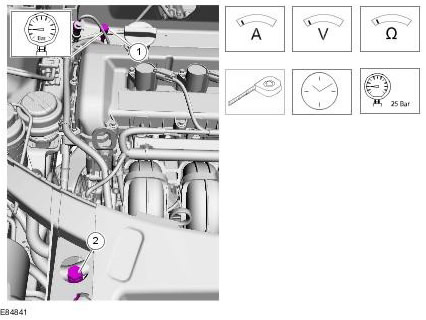
TAS graphics
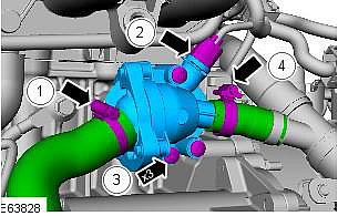
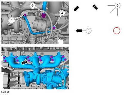
The following colors are used in the drawings:
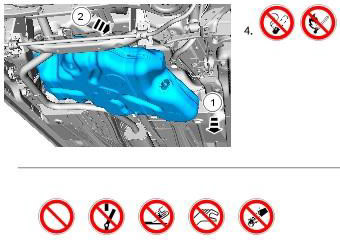
- Blue - shows the target element, i.e. the element to be removed/installed or disassembled/assembled
- Green and Brown - Indicates a secondary element that needs to be detached, removed/installed, or disassembled/assembled before the target element
- Red - shows electrical connectors and fasteners such as nuts, bolts, clamps or clamps
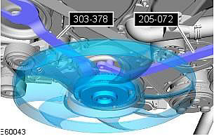
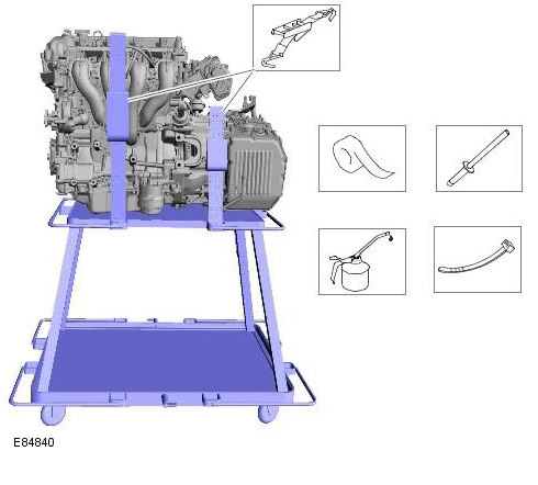
- Pale blue - for special tools and general equipment
Several stages can be displayed in one figure. Numbered arrows are used to indicate the number of electrical connectors and fasteners such as nuts, bolts, clamps, or clamps.
To show hidden elements, some positions in the figure can be shown transparent or sectional images are used.
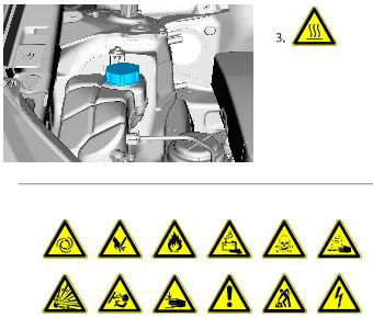
TAS symbols
Symbols are used in graphics and in text to improve the presentation of information. The following paragraphs describe the various types and categories of symbols.
Prohibition symbols report prohibited activities that may cause injury or pose a threat to health and safety.
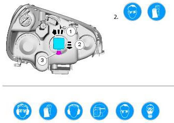
Safety symbols recommend the use of special protective equipment to avoid or reduce the risk or severity of possible injury.
Warning symbols are used to indicate possible risks arising from a particular element or area.
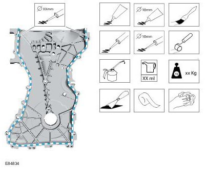
Instruction symbols are used to apply a sealant, lubricant, cleaning agent to the element, to apply a tape or apply a load.
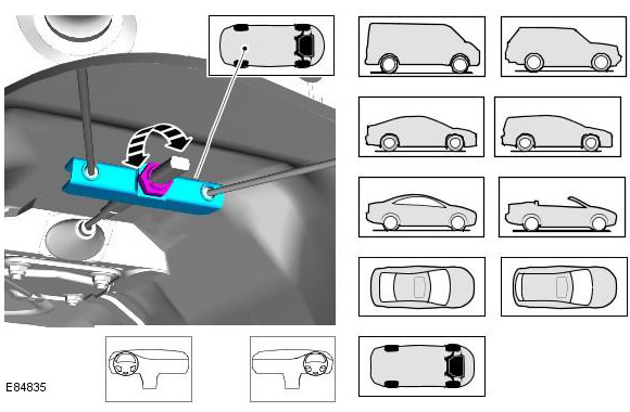
Location symbols are used to show the location of an element or system within a vehicle.
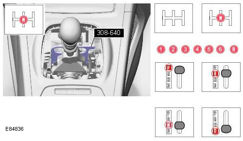
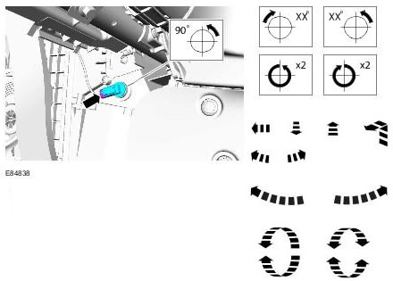
Lever Position Symbols shift or selector lever are used to show which position the gearshift or selector lever should be moved to.
Pointing symbols are used to draw attention to elements and give special instructions, such as the sequence or number of elements, for example. The number of elements is shown by the value inside the arrow. The sequence number is inside the circle. The numbers inside the circles are also used to place special information, such as tightening torques or chemicals of a particular element.
Move Arrows are used to show three-dimensional movements or rotational movements. If necessary, the specific values of these movements are displayed inside the symbol.
Standard Tool Symbols recommend the use of specific standard tools. If necessary, these symbols may include the dimension of the tool.
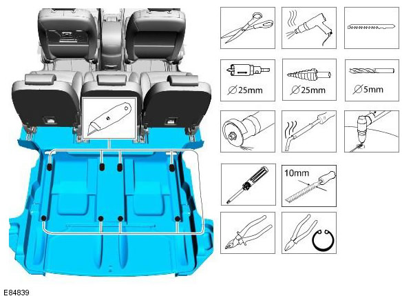
The following graphic illustrates the character set that is used for providing detailed information about where to apply the material.
Dimension symbols tell you where specific measurements need to be taken. These symbols may include specific meanings as needed.
Special tools and tightening torques
Special tools in the drawings will be accompanied by the tool number. Number (A) special tool, general equipment, material (s) and tightening torque values used in the procedure item will be shown in the text column.
Comments on this article