Dismantling
1. Remove the rear drive shaft.
DRIVE SHAFTS, REPAIR WORKS, Drive shaft - rear.
2. Place the drive shaft in a vise.
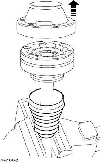
3. Remove and discard the dust cover from the drive shaft.
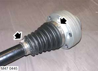
4. Remove and discard both straps securing the protective boot.
5. Slide the protective boot over the shaft to access the pivot.
6. Remove excess grease from the drive shaft.
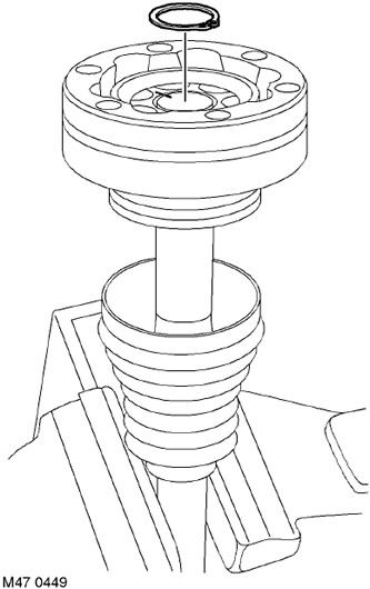
7. Remove and discard the driveshaft circlip.
8. Mark the drive shaft and joint for reassembly.
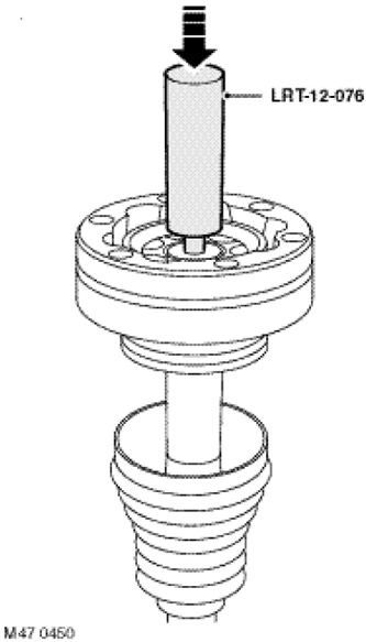
9. While maintaining the CV joint, use tool LRT-12-076 to remove the joint from the drive shaft.
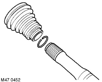
10. Remove and discard the circlip holding the pivot to the drive shaft.
11. Remove the protective cover from the shaft.
Assembly
1. Wipe the drive shaft and constant velocity joint.
2. Put a protective cover on the shaft.
3. Install a new pivot retaining ring on the drive shaft.
4. Install the joint on the drive shaft so that the mounting marks of the shaft and the joint coincide.
5. Install a new circlip on the end of the drive shaft.
6. Lubricate the hinge with grease from the tube.
7. Put on a protective cover on the hinge and fix it on the hinge and a shaft new collars.
8. Install a new dust cover on the drive shaft.
9. Reinstall the rear drive shaft.
DRIVE SHAFTS, REPAIR WORKS, Protective cover - constant velocity joint - outer - rear.
Comments on this article