Contents: Dismantling ⇩ Assembly ⇩
Before disconnecting the battery, make sure that all requirements and conditions contained in the section on disconnecting the battery are met.
GENERAL INFORMATION, Precautions when working with electrical equipment.
Dismantling
1. Place the vehicle on a lift.
2. Disconnect the negative battery terminal.
3. Drain the coolant from the engine.
COOLING SYSTEM: V8 engine, ADJUSTMENTS, Draining coolant, flushing the system and filling.
4. Drain the oil from the engine and remove the filter element from the oil filter housing.
MAINTENANCE, SERVICE OPERATIONS, Engine Oil and Oil Filter - V8 Engine.
5. Remove the right exhaust manifold.
EXHAUST MANIFOLD AND EXHAUST SYSTEM: V-8 Engine, REPAIR, Right Exhaust Manifold Gasket(s).
6. Disconnect the cooling system hoses from the liquid pump.
COOLING SYSTEM: V8 engine, REPAIR WORK, Tubes connecting the distribution pipe to the cooling system pump.
7. Remove the right valve timing adjuster.
V8 Engine, REPAIR WORK, Valve timing control (VCC). Right cylinder head.
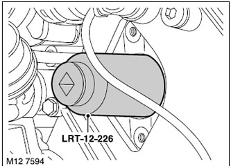
8. Install the LRT-12-226 socket head onto the valve timing control solenoid valve and remove the valve.
CAUTION: When removing the solenoid valve, do not allow oil to come into contact with the drive belts.
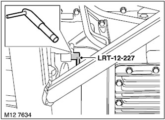
9. Remove the LRT-12-227 pin from the retainer hole.
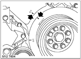
10. Turn the crankshaft counterclockwise to the 45° TDC position.
NOTE: While turning the crankshaft, tighten the camshaft timing chain and keep it taut.
11. Remove tools LRT-12-223/6, LRT-12-223/5, LRT-12-223/2 and LRT-12-223/1 from the right cylinder head camshafts.
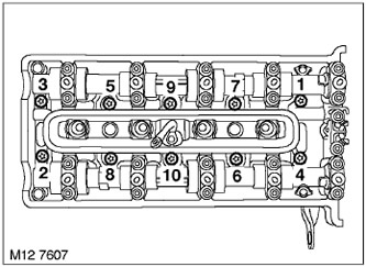
12. Loosen the 10 cylinder head mounting bolts in the sequence shown in the figure.
13. Discard the head bolts and remove the 10 bolt washers.
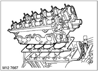
14. With the help of a partner, remove the cylinder head.
15. Discard the cylinder head gasket.
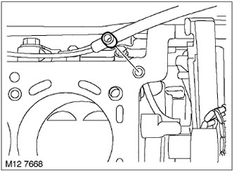
16. Discard the O-ring on the cylinder block.
Assembly
1. Clean the cylinder head, cylinder block, pins and pin holes. If necessary, remove any remaining sealant with a hardwood scraper. Make sure that no sealant remains in the oil or water passages or in the threaded seats.
CAUTION: Make sure that there is no oil or coolant left in the threaded seats of the cylinder block. Failure to do so may damage the cylinder block when tightening the head bolts.
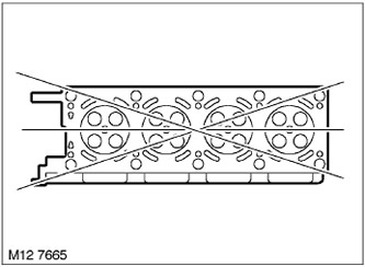
2. Using a straightedge and feeler gauge, check the linearity of the lower plane of the head in the directions shown in the figure.
TECHNICAL SPECIFICATIONS, Engine - V8.
3. Install a new O-ring onto the cylinder block.
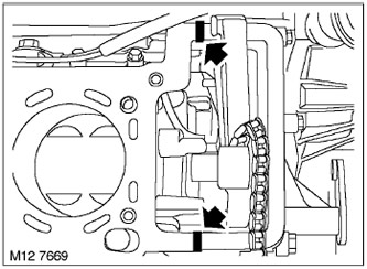
4. Apply STC 50550 sealant to the areas shown in the figure.
5. Place the new cylinder head gasket onto the dowel pins in the cylinder block.
6. With the help of a partner, place the head on the block, making sure that it lands on the pins.
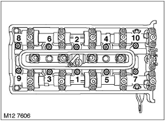
7. Replace the head bolt washers and screw in new bolts. Tighten the head bolts to 30 N·m in the sequence shown in the figure. Using an angle torque wrench, tighten the bolts an additional 80° in the same sequence, and then another 80°.
NOTE: Do not attempt to remove the special coating from new bolts.
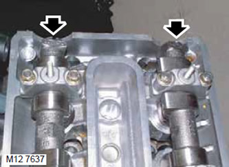
8. Carefully turn the camshafts until the letters and cylinder numbers located at the rear of the shafts are facing upwards.
NOTE: Apparent incorrect camshaft position does not indicate incorrect valve timing.
9. Loosen the bolt securing the LRT-12-223/2 mandrel to the LRT-12-223/1 mandrel.
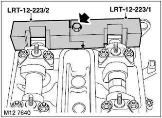
10. Install the LRT-12-223/2 and LRT-12-223/1 mandrels onto the rear of the right cylinder head camshafts and tighten the bolt.
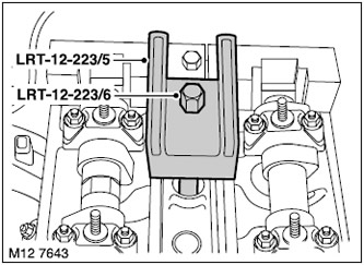
11. Install the LRT-12-223/5 and LRT-12-223/6 drifts onto the right cylinder head and tighten the LRT-12-223/6 drift using the spark plug threaded seat.
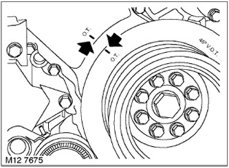
12. Turn the crankshaft clockwise until the TDC marks align.
NOTE: While turning the crankshaft, tighten the camshaft timing chain and keep it taut.
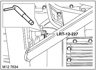
13. Insert pin LRT-12-227 through the hatch and fix the flywheel in the TDC position.
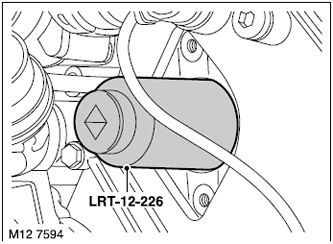
14. Install the LRT-12-226 socket head onto the camshaft timing control solenoid valve and screw in the valve.
15. Install the right valve timing adjuster.
V8 Engine, REPAIR WORK, Valve timing control (VCC). Right cylinder head.
16. Connect the cooling system hoses to the liquid pump.
COOLING SYSTEM: V8 engine, REPAIR WORK, Tubes connecting the distribution pipe to the cooling system pump.
17. Install the right exhaust manifold.
EXHAUST MANIFOLD AND EXHAUST SYSTEM: V-8 Engine, REPAIR, Right Exhaust Manifold Gasket(s).
18. Screw on the new oil filter and fill the engine with oil.
MAINTENANCE, SERVICE OPERATIONS, Engine Oil and Oil Filter - V8 Engine.
19. Fill the cooling system with coolant.
COOLING SYSTEM: V8 engine, ADJUSTMENTS, Draining coolant, flushing the system and filling.
20. Connect the negative battery terminal.
Comments on this article