GENERAL INFORMATION, Precautions when working with electrical equipment.
Dismantling
1. Open the hood, lift it up and secure it in an upright position.
2. Disconnect "negative" battery terminal.
3. Remove the air inlet.
HEATING AND VENTILATION, REPAIR WORKS, Air intake box.
4. Relieve residual pressure in the fuel supply system.
V8 FUEL SUPPLY, ADJUSTMENTS AND MAINTENANCE, Relief Pressure Relief.
5. Remove the refrigerant from the air conditioning system.
AIR CONDITIONING SYSTEM, AIR CONDITIONER DRAINAGE, REFRIGERANT RECOVERY AND CHARGING, Air Conditioner Emptying - Refrigerant Recovery and Charging.
6. Remove the combined mass air flow/intake air temperature sensor.
ENGINE MANAGEMENT SYSTEM: V8 engine, REPAIRS, Sensors: integrated mass air flow sensor (MAF) and intake air temperature (IAT).
7. Raise the front of the vehicle and install safety stands.
WARNING: Do not work under a vehicle that is only supported by a jack. Always install safety props.
8. Drain the engine coolant.
COOLING SYSTEM: V8 engine, ADJUSTMENTS, Coolant drain, system flush and fill.
9. Remove the viscous fan clutch.
COOLING SYSTEM: V8 engine, REPAIR WORK, Viscous fan clutch.
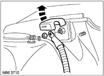
10. Remove the battery cover, unscrew the nut and remove from the battery "positive" terminal.
11. Remove the right cover of ignition coils.
ENGINE MANAGEMENT SYSTEM: V8 engine, REPAIR WORK, Right row ignition coil cover.
12. Remove the left cover of ignition coils.
ENGINE MANAGEMENT SYSTEM: V8 engine, REPAIR WORK, Left row ignition coil cover.
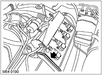
13. Take away from the engine a tube of ventilation of differential.
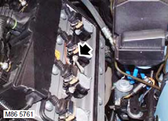
14. Turn away a nut and remove a wire "masses" from the left valve cover.
15. Turn away a nut and remove a wire "masses" from the right valve cover.
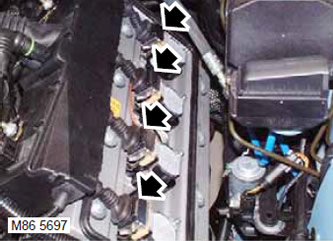
16. Disconnect the pads from the ignition coils.
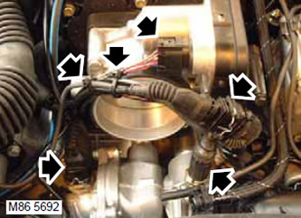
17. Disconnect the connectors from the throttle body, thermostat heater, camshaft position sensor, and coolant temperature sensor.
18. Cut 2 clamps securing the engine harness to the throttle body and release the harness.
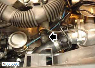
19. Disconnect the electrical connector from the VCC solenoid valve on the right cylinder head.
20. Release the VCC solenoid valve connector from the clamp.
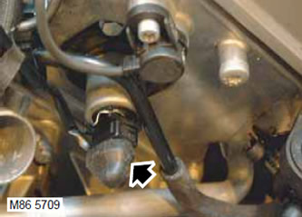
21. Disconnect the electrical connector from the left cylinder head VCC solenoid valve.
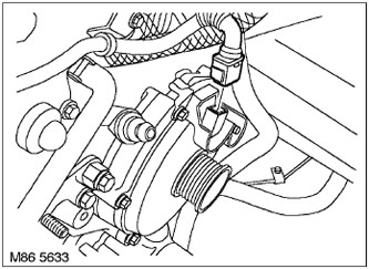
22. Disconnect the block from the generator.
23. Release the wiring harness from 4 clamps.
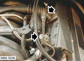
24. Disconnect the connectors from the left camshaft position sensor and from the knock sensor.
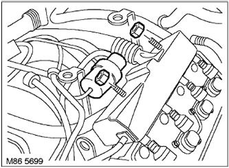
25. Turn off 2 nuts of fastening of a plait of management of atomizers of the left head to a fuel stage, remove a vacuum receiver and an arm from a hairpin and take aside.
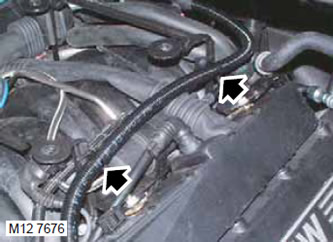
26. Release the generator harness from the two clamps on the brackets of the upper engine casing.
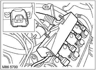
27. Disconnect the connectors from the left row injectors.
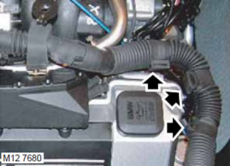
28. Disconnect the motor harness from the clamps and take it away from the valve cover.
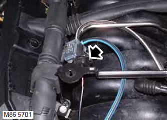
29. Disconnect the connector from the afterburner solenoid valve (SAI).
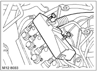
30. Turn away 2 nuts of fastening of a motor plait to an inlet collector, remove washers and remove the electromagnetic valve of system of afterburning from hairpin. Move the valve aside.
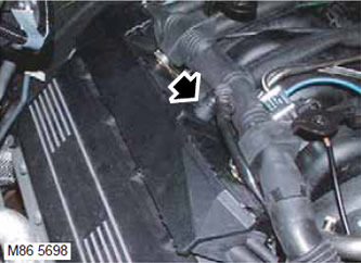
31. Disconnect the block from the right knock sensor.
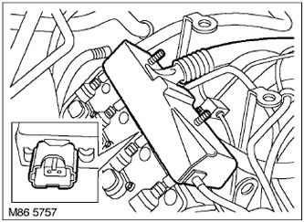
32. Disconnect the connectors from the right row injectors.
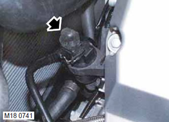
33. Disconnect the connector from the charcoal canister purge valve.
34. Place the engine harness on the right bulkhead.
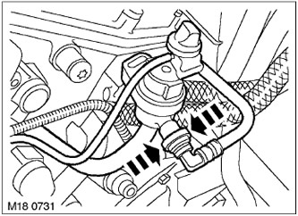
35. Disconnect the hose from the charcoal canister purge valve.
CAUTION: Always plug fittings and openings to keep dirt out of the system.
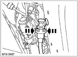
36. Remove the charcoal absorber purge hose.
37. Release the gearbox ventilation hoses from the clamps on the cooling system pipe and take them aside.
38. Loosen the clamps and disconnect the heater hoses from the cooling system pipe.
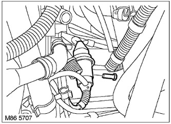
39. Turn away a bolt of fastening of an arm of an electric socket to a flywheel housing, take it aside.
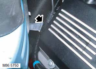
40. Disconnect the connector from the starter wire.
41. Lay a rag near the fuel supply hose so that spilled fuel does not spread.
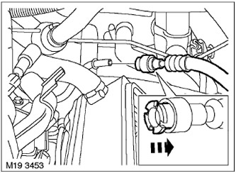
42. Disconnect the fuel supply hose from the fuel rail.
CAUTION: Always plug fittings and openings to keep dirt out of the system.
43. Remove the rags.
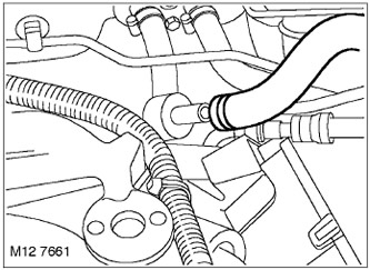
44. Turn away a collar and disconnect a vacuum hose of the amplifier of brakes from the check valve.
CAUTION: Always plug fittings and openings to keep dirt out of the system.
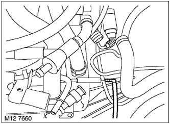
45. Disconnect the vacuum hose from the intake manifold.
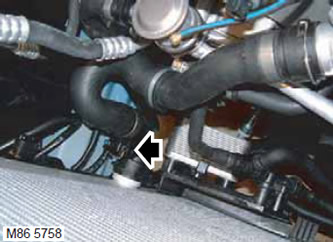
46. Disconnect the electrical connector on the lower radiator hose.
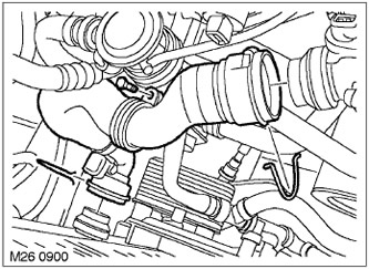
47. Turn away a bolt of fastening of the lower hose of a radiator to an arm, turn away collars and remove the lower hose of a radiator.
48. Loosen the clamp and disconnect the top hose from the radiator.
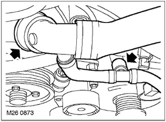
49. Loosen the clamp and disconnect the upper radiator hose from the engine cooling system pump and the generator housing.
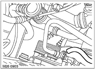
50. Turn away a collar of fastening of the top hose of a radiator to a tee and remove the top hose.
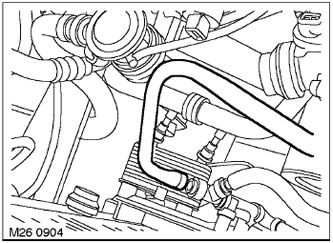
51. Loosen the clamp and disconnect the cooling system hose from the tee.
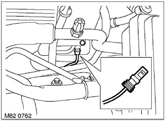
52. Disconnect the connector from the cooling system compressor.
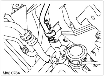
53. Turn away a bolt of fastening of a hose of the central air to the compressor and disconnect a hose. Dispose of the O-ring.
WARNING: Plug all A/C hoses immediately to prevent contamination of the system.
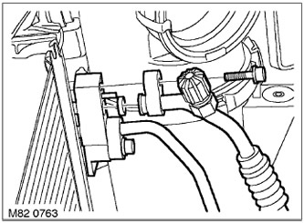
54. Turn away a bolt of fastening of a hose of the central air to the condenser and disconnect a hose. Dispose of the O-ring.
WARNING: Plug all A/C hoses immediately to prevent contamination of the system.
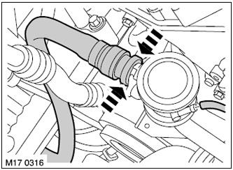
55. Disconnect 2 hoses from the air flow control valve.
CAUTION: Always plug fittings and openings to keep dirt out of the system.
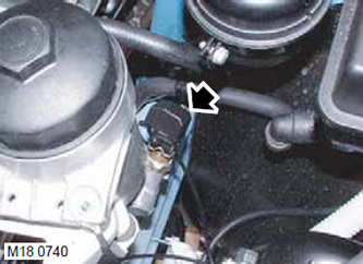
56. Disconnect the connector from the contact oil pressure sensor.
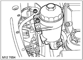
57. Turn away 2 nuts of fastening of the case of the oil filter and remove the case from an arm.
58. Take the filter housing with hoses to the side and fix it on the engine.
59. Install a container to collect the power steering fluid (PAS).
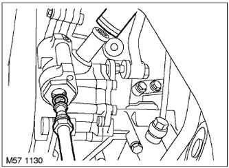
60. Loosen the clamp and disconnect the cooling system hose from the power steering pump. Loosen the union nut and disconnect the pressure hose from the power steering pump. Dispose of the O-ring.
CAUTION: Always plug fittings and openings to keep dirt out of the system.
61. Remove the container from under the power steering pump.
62. Turn away 4 bolts of fastening of an air guard of the main transfer to a stretcher and remove a guard.
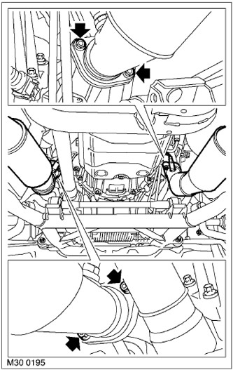
63. Turn away 4 nuts of fastening of flanges of reception pipes to exhaust manifolds. Dispose of the nuts.
64. Remove the exhaust pipes from the exhaust manifolds.
65. Remove the front wheels.
66. Remove the right drive shaft.
DRIVE SHAFTS, REPAIR WORKS, Drive shaft - front - right.
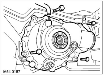
67. Remove the main gear crankcase ventilation hose. Remove the 4 main gear mounting bolts and remove the main gear from the engine sump.
NOTE: The mounting bolt located above the final drive gear remains in the final drive housing.
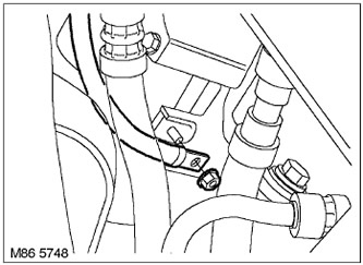
68. Disconnect "negative" battery terminal.
69. Remove the crankshaft position sensor.
ENGINE MANAGEMENT SYSTEM: V8 engine, REPAIRS, Sensors: crankshaft position sensor (CKP).
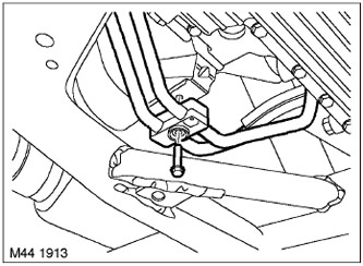
70. Turn away a bolt of fastening of tubes of a radiator of cooling of transmission oil and remove tubes from an arm.
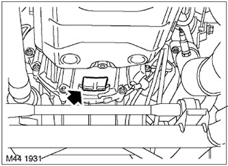
71. Remove the plug from the bottom of the flywheel housing to expose the torque converter.
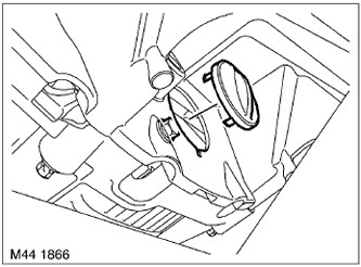
72. Remove the plug from the flywheel housing to expose the torque converter mounting bolts.
73. Rotating the crankshaft, unscrew the 4 bolts securing the torque converter to the drive disk.
74. Take away the hydrotransformer from a leading disk.
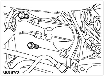
75. Turn away 2 bolts of fastening of a starter and remove a starter.
NOTE: The starter remains on the engine.
76. Establish a supporting rack under a transmission.
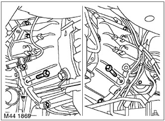
77. Turn away 8 bolts of fastening of a transmission to the engine.
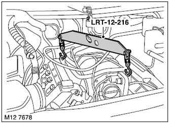
78. Attach the LRT-12-216 yoke to the engine lifting eyes.
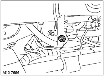
79. Turn away a nut of fastening of the right arm of the engine to a support.
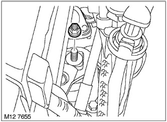
80. Turn away a nut of fastening of the left arm of the engine to a support.
81. Put the chain on the lifting eyes and select the engine weight.
82. Raise the engine so that it is completely off the supports.

83. Turn out two top bolts like Torx of fastening of a case of AKP.
84. Release the engine from the guide pins, carefully lift it and take it away from the car.
ATTENTION: Do not allow the engine to come into contact with the radiator, so as not to damage the latter.
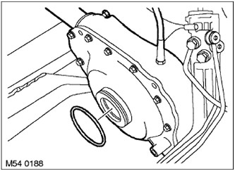
85. Dispose of the final drive O-ring.
Assembly
1. Wipe the mating surfaces of the torque converter and drive plate.
2. Wipe the mating surfaces of the engine and gearbox, dowel pins and pin sockets.
3. Wipe the mating surfaces of the final drive housing and engine sump.
4. Fit a new O-ring to the final drive housing and lubricate it with clean oil.
5. With the help of a partner, carefully install the engine on the gearbox. Make sure that the torque converter centering bushing fits accurately and that the pins fit into the sockets.
NOTE: When installing the engine, run it behind the mating surface of the final drive.
6. Make sure the torque converter is fully engaged with the transmission.
7. Screw in 8 Torx screws securing the automatic transmission to the engine and tighten them to a torque of 45 Nm.
8. Reinstall the starter, tighten the bolts of its fastening to 45 Nm.
9. Screw in 2 upper bolts of fastening of a case of a flywheel and tighten them the moment of 25 Нм.
10. Remove the jack from under the gearbox.
11. Lower the engine onto stands.
12. Remove lifting chains.
13. Screw 2 nuts securing the engine brackets to the supports and tighten them to a torque of 100 Nm.
14. Remove the lifting beam.
15. Screw in 8 bolts of fastening of a leading disk to the hydrotransformer and tighten them with the moment of 45 Нм.
16. Install the plugs on the flywheel housing.
17. Wipe the mating surfaces of the intake pipes and exhaust manifolds.
18. Install downpipes to exhaust manifolds
19. Screw on 4 new nuts of fastening of reception pipes to final collectors and tighten them with the moment of 45 Нм.
20. Establish the main transfer on the pallet of the engine and tighten 4 bolts of fastening. Tightening torque 45 Nm.
21. Attach the ventilation hose to the final drive housing.
22. Connect the wire to the motor "masses" and tighten the fastener.
23. Install the final drive air shield on the subframe and tighten the bolts to 45 Nm.
24. Install the right drive shaft.
DRIVE SHAFTS, REPAIR WORKS, Drive shaft - front - right.
25. Install a new O-ring on the power steering pump fitting and connect the hose to the pump by tightening the nut to 25 Nm.
26. Put the low pressure hose on the power steering pump and secure it with a new clamp.
27. Install the oil filter housing on the bracket and tighten the fastening nuts.
28. Connect the connector to the oil pressure switch.
29. Connect the hoses to the afterburner solenoid valve.
30. Install new O-rings on the air conditioning hoses and lubricate them with clean oil added to the refrigerant.
31. Install hoses to condenser and compressor. Screw in the bolts securing the air conditioning hoses to the condenser and compressor and tighten them to a torque of 25 Nm.
32. Connect the electrical connector to the air conditioning compressor.
33. Attach a hose of system of cooling to a tee and fix it with a collar.
34. Put on the upper radiator hose and secure it with clamps.
35. Put on the lower radiator hose and secure it with clamps.
36. Connect the electrical connector on the lower radiator hose.
37. Attach a vacuum hose to an inlet collector.
38. Connect the vacuum hose to the check valve of the vacuum brake booster and secure it with a new clamp.
39. Wipe fuel hose connectors.
40. Attach the fuel supply hose to the fuel rail.
41. Connect the connector to the starter wire.
42. Install the connector with the bracket on the flywheel housing and tighten the mounting bolt.
43. Attach the cooling system hoses to the liquid pipe and secure them with clamps.
44. Insert the gearbox ventilation tubes into the supporting clamps.
45. Install the charcoal canister purge hose.
46. Install the engine harness on the engine.
47. Connect the connector to the charcoal canister purge valve.
48. Install the washer on the fuel injector harness stud.
49. Install and secure the engine harness with clamps on the bracket.
50. Attach the connectors to the nozzles of the right row.
51. Connect the connectors to the left row injectors.
52. Attach the generator harness to the two clamps on the upper engine cover.
53. Install the fuel hose with bracket on the left-hand injector harness stud.
54. Attach the vacuum reservoir with the bracket to the left row injector harness mounting stud.
55. Screw 2 nuts securing the injector harness to the intake manifold and tighten the nuts.
56. Attach the block to the knock sensor.
57. Attach the shoe to the crankshaft position sensor.
58. Fasten the generator harness in four clamps.
59. Connect the connector to the generator.
60. Connect the connector to the afterburner solenoid valve.
61. Connect the connectors to the solenoid valves of the valve timing regulators.
62. Connect the connectors to the throttle body, thermostat heater, right camshaft position sensor, and coolant temperature sensor.
63. Install the engine harness on the throttle body and secure it with new flexible clamps.
64. Put the connectors on the ignition coils.
65. Put on the wires "masses" on the right and left valve covers and tighten the nuts.
66. Attach the final drive ventilation hose to the left valve cover.
67. Install the left cover of the ignition coils.
ENGINE MANAGEMENT SYSTEM: V8 engine, REPAIR WORK, Left row ignition coil cover.
68. Establish the right cover of coils of ignition.
ENGINE MANAGEMENT SYSTEM: V8 engine, REPAIR WORK, Right row ignition coil cover.
69. Install the viscous fan clutch.
COOLING SYSTEM: V8 engine, REPAIR WORK, Viscous fan clutch.
70. Install the front wheels and tighten the fastening nuts to 140 Nm.
71. Remove the safety props and lower the front of the vehicle.
72. Install the combined mass air flow/intake air temperature sensor.
ENGINE MANAGEMENT SYSTEM: V8 engine, REPAIRS, Sensors: integrated mass air flow sensor (MAF) and intake air temperature (IAT).
73. Fill the air conditioning system.
AIR CONDITIONING SYSTEM, AIR CONDITIONER DRAINAGE, REFRIGERANT RECOVERY AND CHARGING, Air Conditioner Emptying - Refrigerant Recovery and Charging.
74. Replace the air inlet.
HEATING AND VENTILATION, REPAIR WORKS, Air intake box.
75. Put the terminal on "positive" battery pole piece, tighten the nut to 18 Nm and put on the cover.
76. Attach "negative" battery terminal.
77. Fill the cooling system with coolant.
COOLING SYSTEM: V8 engine, ADJUSTMENTS, Coolant drain, system flush and fill.
78. Bleed the power steering system.
STEERING, ADJUSTMENTS, Power Steering (PAS) - removal of air.
79. Close the hood.
Comments on this article