car logo Ford
car logo Volkswagen
car logo BMW
car logo Opel
car logo Audi
car logo Toyota
car logo Peugeot
English Русский
Български
Беларускі
Український
Српски
Hrvatski
Română
Polski
Slovenský
Magyar


Main
Freelander
Discovery
Range Rover
Defender
Contacts
Articles

Rear engine mount (Range Rover 3)

 
  • Main
  • Range Rover
  • Range Rover 3
  • Power unit
  • Petrol engine V8
  • Rear engine mount
 
        0  
Contents: Dismantling ⇩ Assembly ⇩
Before disconnecting the battery, make sure that all requirements and conditions contained in the section on disconnecting the battery are met.

GENERAL INFORMATION, Precautions when working with electrical equipment.

Dismantling


1. Place the vehicle on a lift.

2. Disconnect the negative battery terminal.

3. Raise the car on a lift.

4. Remove the exhaust system.

EXHAUST MANIFOLD AND DUCT SYSTEM: V-8 Engine, REPAIR WORK, Exhaust system and suspension components.
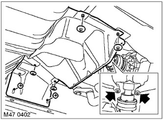
5. Unscrew the 8 nuts securing the middle heat shield and remove the shield.
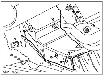

5. Unscrew the 8 nuts securing the middle heat shield and remove the shield.

6. Unscrew 5 nuts and remove the right heat shield.
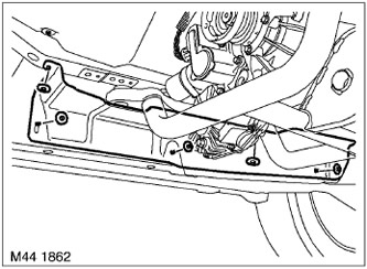

6. Unscrew 5 nuts and remove the right heat shield.

7. Unscrew 5 nuts and remove the left heat shield.
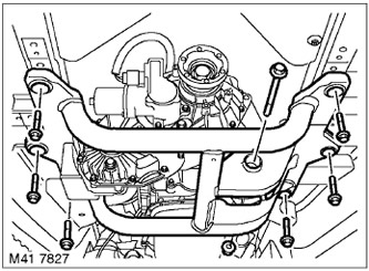

7. Unscrew 5 nuts and remove the left heat shield.


8. Install the support stand under the gearbox.


8. Install the support stand under the gearbox.

9. Unscrew the bolt and nut securing the support to the cross beam.

10. Remove the 6 cross member mounting bolts and remove the cross member.
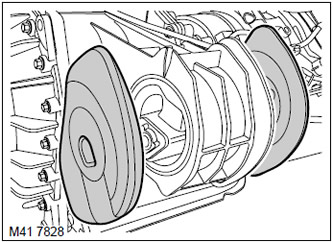
11. Remove the silent blocks from the support.

11. Remove the silent blocks from the support.

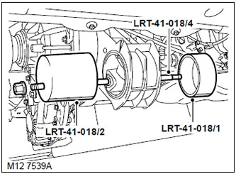
12. Apply molybdenum grease to the center screw of the LRT-41-018/4 tool and assemble the tool to…


12. Apply molybdenum grease to the center screw of the LRT-41-018/4 tool and assemble the tool to remove the support from the transfer case as shown in the figure.


CAUTION: Make sure the alignment indicator is in the lowest position. The position indicator is the machined flats on the LRT-41-018/1 and LRT-41-018/2 components of the fixture.


Assembly


1. Wipe all mounting and mating surfaces.

2. Lubricate the new support and the drilled hole in the transfer case housing to facilitate assembly.
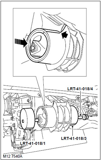
3. Position the new support at the rear of the transfer case and begin installation. The support…


3. Position the new support at the rear of the transfer case and begin installation. The support should move smoothly and the mounting marks should line up with each other.

NOTE: To facilitate alignment, duplicate the mounting mark on the side surface of the support.


4. Lubricate the middle screw of the LRT-41-018/4 with molybdenum disulfide grease and assemble the transfer case mount installer as shown in the figure. Start with the center screw fully out and when the mount is about 75% in, shorten the center screw by screwing it all the way into the LRT-41-018/1 plate. This will help prevent the LRT-41-018/4 center screw from hitting the transmission pan.

CAUTION: Make sure the alignment indicator is in its lowest position.


5. Make sure that the support is installed without distortions. If necessary, restore parallelism by hitting the base of the support with a mallet.


6. Install silent blocks.

7. Install the crossbar onto the support, tighten the bolt and nut, but do not tighten them yet.

8. Raise the gearbox with a jack.

9. Screw in the cross member mounting bolts and tighten them to a torque of 68 Nm.

The article was copied from this resource LRman.ru

10. Remove the jack from under the gearbox.

11. Tighten the nut and bolt securing the support to the cross member to a torque of 100 Nm.

12. Replace the left heat shield and secure it with nuts.

13. Replace the right heat shield and secure it with nuts.

14. Install the middle heat shield and tighten its mounting nuts.

15. Reinstall the exhaust system.

EXHAUST MANIFOLD AND DUCT SYSTEM: V-8 Engine, REPAIR WORK, Exhaust system and suspension components.


16. Connect the negative battery terminal.


This article is available at russian, bulgarian, belarusian, ukrainian, serbian, croatian, romanian, polish, slovak, hungarian
Article review: Platon Fedorov


Previous articles
Checking oil pressure
Crankshaft pulley
Front crankshaft oil seal
Rear crankshaft oil seal
Left cylinder head gasket
Right cylinder head gasket
Left cylinder head valve cover gasket
Right cylinder head valve cover gasket

Current article
Rear engine mount

Next articles
Left engine mount
Right engine mount
Torque converter drive disc
Oil filter
Oil dipstick tube
Oil receiver with mesh filter
Oil pump
Removal the lower part of the oil pan


Similar articles from Land Rover repair manuals:
• Upper Engine Mount Insulator Freelander 2 (2006-2014)
• Lower engine mount cross member Freelander 1 (1997-2006)
• Left engine mount Discovery 3 (2004-2009)
• Left engine mount — removal and installation Defender 2007+ (2007-2016)

Comments on this article


No comments yet


How much will 15 + 28 =


Range Rover 3 
  • General information
  • Using the manual
  • Precautionary measures
  • Repair techniques
  • Identification codes
  • Specifications
  • Tightening torques
  • Materials
  • Maintenance
  • Power unit
  • Diesel engine TD6
  • Petrol engine V8
  • Emission reduction TD6
  • Emission reduction V8
  • Engine management TD6
  • Engine management V8
  • Fuel supply TD6 engine
  • Fuel supply V8 engine
  • Engine cooling TD6
  • Engine cooling V8
  • Exhaust system TD6
  • Exhaust system V8
  • Transfer case
  • Automatic gearbox GM-5L40-E
  • Automatic gearbox ZF 5HP24
  • Chassis
  • Drive shafts
  • Main gear
  • Front axle gear
  • Steering
  • Front suspension
  • Rear suspension
  • Brake system
  • Body and coating
  • Passenger safety
  • Doors and windows
  • Exterior details
  • Interior details
  • Glasses
  • Seats
  • Sunroof
  • Body geometry
  • Body repair
  • Corrosion protection
  • Electrical equipment
  • Heating and ventilation
  • Conditioning
  • Windshield wipers and washers
  • Starting and charging system
  • Lighting and headlights
  • Electronic blocks
  • Entertainment system
  • Wiring harnesses


LRman.ru © 2013-2026 | Mobile version | Free Lander | Discovery | Range Rover | Defender | Contacts | | Sitemap |
Car repair and service instructions Land Rover: Freelander, Discovery, Range Rover, Defender
We use cookies to make pages load faster and provide a more user-friendly experience 🍪