Contents: Dismantling ⇩ Assembly ⇩
Before disconnecting the battery, make sure that all requirements and conditions contained in the section on disconnecting the battery are met.
GENERAL INFORMATION, Precautions when working with electrical equipment.
Dismantling
1. Disconnect the negative battery terminal.
2. Raise the front of the vehicle and support it with safety stands.
3. Remove the air intake receiver.
HEATING AND VENTILATION, REPAIR WORKS, Air intake box.
4. Remove the air intake hose.
ENGINE MANAGEMENT SYSTEM: V8 engine, REPAIR WORK, Hose connecting the air flow sensor to the throttle body.
5. Remove the lower protective cover.
EXTERIOR PARTS, REPAIR WORK, Engine protection - front.
6. Unscrew the 4 bolts securing the main gear air shield to the subframe and remove the shield.
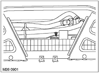
7. Remove the bolt securing the fan shroud to the radiator.
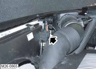
8. Release the additional cooling system fan connector from the fan housing.
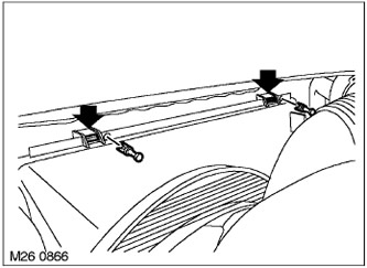
9. Remove the fan shroud fasteners.
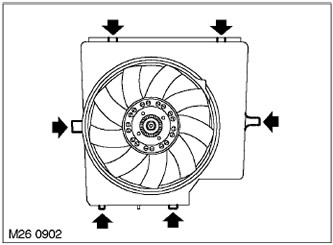
10. Remove the fan shroud from the radiator.
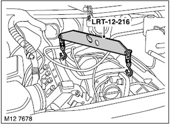
11. Install the LRT-12-216 fixture onto the engine lifting eyes.
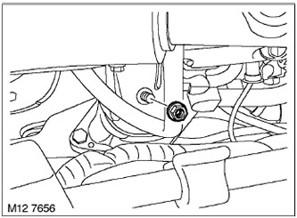
12. Unscrew the nut securing the right engine bracket to the support.
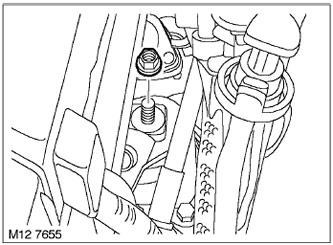
13. Unscrew the nut securing the left engine bracket to the support.
14. Remove the front wheels.
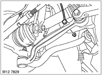
15. Loosen the nut and disconnect the rod from the left front suspension height sensor.
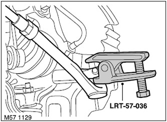
16. Unscrew the nuts securing the right and left ball joints of the tie rod ends to the steering arms. Dispose of the nuts.
17. Using the LRT-57-036 tool, disconnect the cross rods from the steering arms.
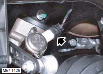
18. Remove the steering angle sensor connector block.
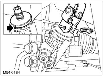
19. Mark the position in which the intermediate steering shaft is installed. Loosen the intermediate steering shaft clamp bolt and disconnect it from the rack and pinion mechanism.
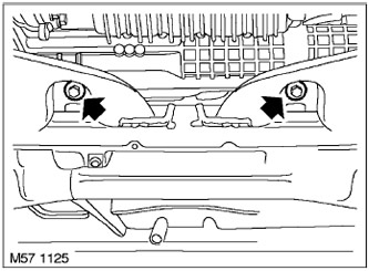
20. Remove the 2 bolts and 2 nuts securing the rack and pinion mechanism. Discard the bolts and nuts.
21. Remove the rack and pinion mechanism from the front subframe and move it forward.
22. Place rigging chains on the engine lifting eyes and lift the engine only enough to clear the engine mount.
CAUTION: To avoid damaging the radiator, support and keep the fan shroud away from the radiator as it rises with the engine.
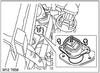
23. Unscrew the 2 bolts securing the left engine support to the subframe and remove the support. Dispose of the bolts.
NOTE: The left engine mount is removed from under the left front wheel well, through the opening in the front subframe.
Assembly
1. Wipe all mounting and mating surfaces.
2. Install the left engine mount to the subframe and tighten the new bolts. Tightening torque is 56 N·m.
3. Lower the engine onto the supports.
NOTE: When lowering the engine onto the support, guide the fan shroud into place.
4. Install the rack and pinion mechanism onto the front subframe, tighten the new bolts and nuts to 100 Nm, then turn them 90° further.
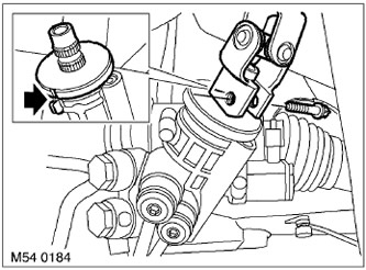
5. Connect the intermediate steering shaft to the rack and pinion mechanism and tighten the terminal clamp bolt to a torque of 24 N·m.
NOTE: When installing the intermediate shaft, ensure that it is correctly positioned in relation to the rack and pinion mechanism.
6. Connect the connector to the steering angle sensor connector.
7. Connect the tie rod ends to the steering arms, tighten the new nuts to a torque of 55 N·m.
8. Connect the rod to the suspension height sensor and tighten the nut.
9. Reinstall the front wheels and tighten the nuts. Tightening torque 140 Nm.
10. Screw on the 2 nuts securing the engine brackets to the supports and tighten them to a torque of 100 Nm.
11. Remove the rigging chains.
12. Remove the rigging crossbar.
13. Attach the fan shroud to the radiator by installing the fasteners.
14. Secure the additional cooling system fan connector to the fan housing.
15. Tighten the screw securing the fan shroud to the radiator.
16. Reinstall the lower protective cover.
EXTERIOR PARTS, REPAIR WORK, Engine protection - front.
17. Install the final drive air shield onto the subframe and tighten the bolts to 45 Nm.
18. Remove the safety stands and lower the front of the vehicle.
19. Reinstall the air intake hose.
ENGINE MANAGEMENT SYSTEM: V8 engine, REPAIR WORK, Hose connecting the air flow sensor to the throttle body.
20. Install the air intake receiver in place.
HEATING AND VENTILATION, REPAIR WORKS, Air intake box.
21. Connect the negative battery terminal.
Comments on this article