Contents: Dismantling ⇩ Assembly ⇩
Before disconnecting the battery, make sure that all requirements and conditions contained in the section on disconnecting the battery are met.
GENERAL INFORMATION, Precautions when working with electrical equipment.
Dismantling
1. Place the vehicle on a lift.
2. Disconnect the negative battery terminal.
3. Drain the coolant from the engine.
COOLING SYSTEM: V8 engine, ADJUSTMENTS, Draining coolant, flushing the system and filling.
4. Remove the fan protective cover.
COOLING SYSTEM: V8 engine, REPAIR WORK, Viscous fan clutch.
5. Remove the valve cover of the left cylinder head.
V8 engine, REPAIR WORK, Left cylinder head valve cover gasket.
6. Remove the valve cover of the right cylinder head.
V8 engine, REPAIR WORK, Right cylinder head valve cover gasket.
7. Remove 8 spark plugs.
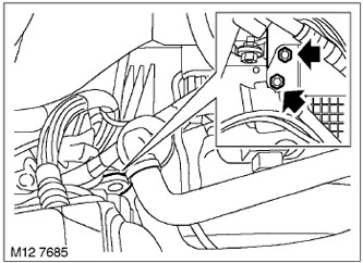
8. Unscrew the 2 bolts securing the rear lifting eye on the right cylinder head and remove the eye.
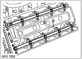
9. Unscrew the 20 nuts securing the 4 oil distribution tubes for lubrication of the camshafts of the left and right cylinder heads and remove the oil distribution tubes.
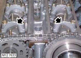
10. Turn the crankshaft so that the camshaft cams on the first cylinder are in the TDC position at the beginning of the working stroke.
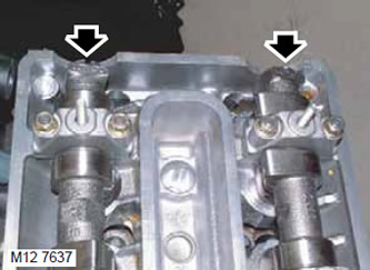
11. The rear of the camshaft may appear to be offset in angle and in the wrong position, even though the cams of the first cylinder are at TDC at the beginning of the power stroke.
NOTE: Apparent incorrect camshaft position does not indicate incorrect valve timing.
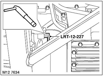
12. Insert pin LRT-12-227 through the hatch and fix the flywheel in the TDC position.
13. Remove the upper front timing cover on the left head.
V8 Engine, REPAIR WORK, Upper Front Timing Belt Cover Left Cylinder Head.
14. Remove the upper front timing cover on the right head.
V8 Engine, REPAIR WORK, Upper Front Timing Belt Cover Right Cylinder Head.
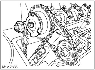
15. Unscrew the nut securing the left head camshaft position sensor disk and remove the disk.
NOTE: This thread is left hand.
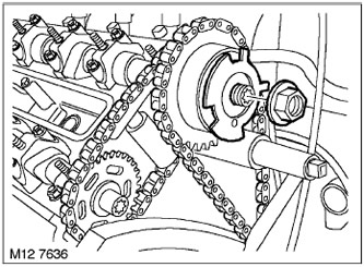
16. Unscrew the nut securing the right head camshaft position sensor disk and remove the disk.
NOTE: This thread is left hand.
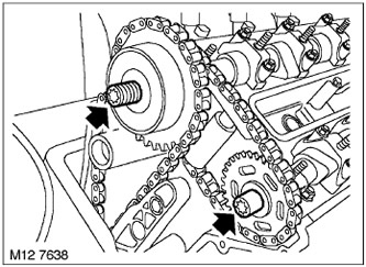
17. Loosen the 2 bolts securing the left head VCC and the left head exhaust camshaft sprocket by half a turn.
NOTE: This thread is left hand.
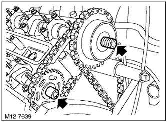
18. Loosen the 2 bolts securing the right head VCC and the right head exhaust camshaft sprocket by half a turn.
NOTE: This thread is left hand.
19. Loosen the bolt securing the LRT-12-223/2 mandrel to the LRT-12-223/1 mandrel.
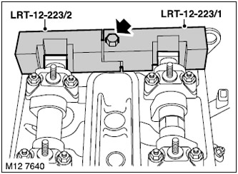
20. Install the LRT-12-223/2 and LRT-12-223/1 mandrels onto the rear of the right cylinder head camshafts and tighten the bolt.
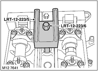
21. Install the LRT-12-223/5 and LRT-12-223/6 drifts onto the right cylinder head and tighten the LRT-12-223/6 drift using the spark plug threaded seat.
22. Loosen the bolt securing the LRT-12-223/4 mandrel to the LRT-12-223/3 mandrel.
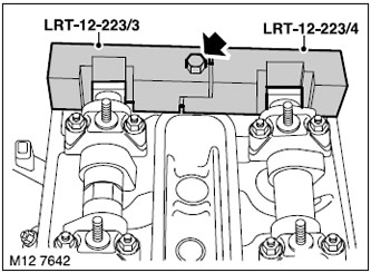
23. Install the LRT-12-223/4 and LRT-12-223/3 mandrels onto the rear of the left cylinder head camshafts and tighten the bolt.
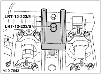
24. Install the LRT-12-223/5 and LRT-12-223/6 mandrels onto the left cylinder head and tighten the LRT-12-223/6 using the spark plug threaded seat.
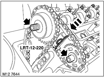
25. Compress the left head exhaust camshaft drive chain tensioner spring, insert the LRT-12-220 pin into the tensioner and unscrew the 2 VCC and exhaust camshaft sprocket mounting bolts.
NOTE: This thread is left hand.
26. Remove the exhaust camshaft sprocket, exhaust camshaft timing chain and left head VCC.
NOTE: To prevent the chain from falling down, secure it to the cylinder head.
Assembly
1. Place the exhaust camshaft chain onto the left head VCC block, insert the exhaust camshaft sprocket into the drive chain.
NOTE: The VCC unit, exhaust camshaft timing chain and exhaust camshaft sprocket do not have timing marks. These components can be installed on the timing chain and camshafts in any position.
2. With the timing chain on the VCC block, install the VCC and exhaust camshaft sprocket onto your camshafts, and install and tighten the 2 mounting bolts until there is no play. NOTE: These are left-hand threads.
3. Compress the exhaust camshaft drive chain tensioner spring and remove the LRT-12-220 pin.
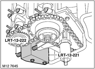
4. Install the LRT-12-221 drift onto the right cylinder head, secure the LRT-12-222 drift onto the LRT-12-221 and tighten by hand.
NOTE: Turn the adjusting bolt only until slight resistance is felt.
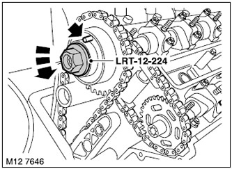
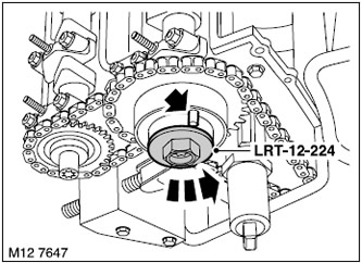
5. Install the LRT-12-224 tool to the left cylinder head VCC and connect the tester between the terminal on the VCC and the stud on the oil distributor tube.
6. Rotate the VCC unit using the LRT-12-224 tool until the rotation force reaches 40 N·m, use a tester to check for continuity.
NOTE: By rotating the VCC by the LRT-12-224 tool, excess oil is removed and the VCC is brought to the stop. The circuit is closed when the VCC reaches the stop.
7. Tighten the left VCC and exhaust camshaft sprocket mounting bolts to 15 Nm and loosen a quarter of a turn.
NOTE: This thread is left hand.
(The original article can be found here www.LRman.ru)
8. Install the LRT-12-224 tool to the VCC of the right cylinder head and connect the tester between the terminal on the VCC and the stud on the oil distributor tube.
9. Rotate the VCC unit using the LRT-12-224 tool until the rotation force reaches 40 N·m, use a tester to check for continuity.
NOTE: By rotating the VCC by the LRT-12-224 tool, excess oil is removed and the VCC is brought to the stop. The circuit is closed when the VCC reaches the stop.
10. Tighten the right VCC and exhaust camshaft sprocket mounting bolts to 15 Nm and loosen a quarter of a turn.
NOTE: This thread is left hand.
11. Adjust the chain tension by tightening the LRT-12-222 tool to 0.7 N·m.
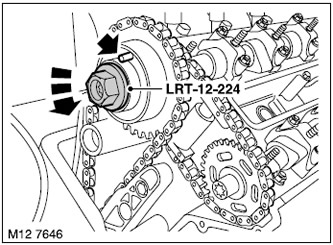
12. Install the LRT-12-224 tool to the left cylinder head VCC and connect the tester between the terminal on the VCC and the stud on the oil distributor tube.
NOTE: When adjusting the chain tension, the VCC will shift and will need to be moved to the left stop.
13. Rotate VCC by LRT-12-224 until the rotation force reaches 40 N·m, use a tester to check the continuity of the circuit.
NOTE: By rotating the VCC by the LRT-12-224 tool, excess oil is removed and the VCC is brought to the stop. The circuit is closed when the VCC reaches the stop.
14. Tighten the left VCC block mounting bolts to 110 N·m and the exhaust shaft sprocket mounting bolt to 125 N·m.
NOTE: This thread is left hand.
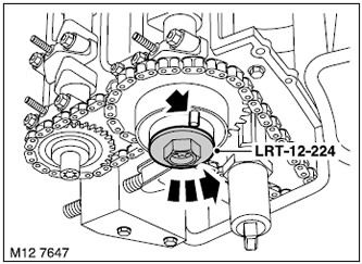
15. Install the LRT-12-224 tool to the VCC of the right cylinder head and connect the tester between the terminal on the VCC and the stud on the oil distributor tube.
NOTE: When adjusting the chain tension, the VCC will shift and will need to be moved to the left stop.
16. Rotate the VCC unit using the LRT-12-224 tool until the rotation force reaches 40 N·m, use a tester to check for continuity.
NOTE: By rotating the VCC by the LRT-12-224 tool, excess oil is removed and the VCC is brought to the stop. The circuit is closed when the VCC reaches the stop.
17. Tighten the right VCC block mounting bolts to 110 N·m and the exhaust shaft sprocket mounting bolt to 125 N·m.
NOTE: This thread is left hand.
18. Install the camshaft position sensor disc and tighten the disc mounting nut by hand.
NOTE: This thread is left hand.
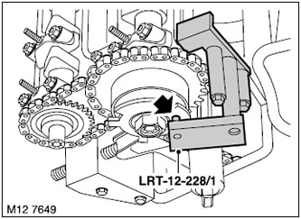
19. Install the LRT-12-228/1 retainer on the right camshaft position sensor disc, screw in the 2 retainer mounting bolts to the right cylinder head and tighten them.
NOTE: To properly adjust the camshaft position (CMP) sensor disc, make sure the retainer is in good contact with the cylinder head surface and the underside of the engine front cover before tightening the retainer bolts. (timing belt covers).
20. Tighten the camshaft position sensor disc mounting nut to 40 Nm and remove the LRT-12-228/1 retainer from the right cylinder head.
NOTE: This thread is left hand.
21. Install the left camshaft position sensor disc and tighten the disc mounting nut by hand.
NOTE: This thread is left hand.
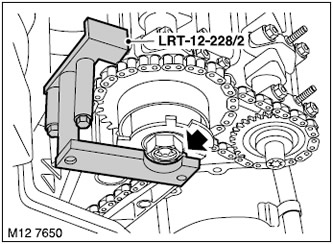
22. Install the LRT-12-228/2 retainer on the left camshaft position sensor disc, screw in the 2 retainer mounting bolts to the left cylinder head and tighten them.
NOTE: To properly adjust the camshaft position sensor disc, make sure the retainer is in good contact with the cylinder head surface and the underside of the engine front cover before tightening the retainer bolts. (timing belt covers).
23. Tighten the camshaft position sensor disc mounting nut to 40 Nm and remove the LRT-12-228/2 retainer from the left cylinder head.
NOTE: This thread is left hand.
24. Remove tools LRT-12-223/6, LRT-12-223/5, LRT-12-223/2 and LRT-12-223/1 from the right cylinder head camshafts.
25. Remove tools LRT-12-223/6, LRT-12-223/5, LRT-12-223/3 and LRT-12-223/4 from the left cylinder head camshafts.
26. Loosen LRT-12-222, remove 2 bolts securing LRT-12-221 to the right cylinder head and remove LRT-12-221.
27. Install the upper front timing cover onto the right cylinder head.
V8 Engine, REPAIR WORK, Upper Front Timing Belt Cover Right Cylinder Head.
28. Install the upper front timing cover onto the left cylinder head.
V8 Engine, REPAIR WORK, Upper Front Timing Belt Cover Right Cylinder Head.
29. Remove the LRT-12-227 pin from the retainer hole.
30. Install 4 oil distribution pipes on the left and right cylinder heads, screw in and tighten 20 mounting bolts.
31. Install the rear lifting eye of the right cylinder head, screw in and tighten the 2 bolts securing it.
32. Install and tighten the 8 spark plugs. Tightening torque 31 N·m.
33. Install the right cylinder head valve cover.
V8 engine, REPAIR WORK, Right cylinder head valve cover gasket.
34. Install the left cylinder head valve cover.
V8 engine, REPAIR WORK, Left cylinder head valve cover gasket.
35. Install the fan guard.
COOLING SYSTEM: V8 engine, REPAIR WORK, Viscous fan clutch.
36. Fill the cooling system with coolant.
COOLING SYSTEM: V8 engine, ADJUSTMENTS, Draining coolant, flushing the system and filling.
37. Connect the negative battery terminal.
Comments on this article