Contents: Removal ⇩ Installation ⇩
Removal
1. Raise the front of the vehicle.
2.
WARNING: Support the vehicle securely. Remove the front wheel.
3. Pull back the front brake caliper hose and pinch the brake hose.
4. Install a container to collect the brake fluid.
5. Loosen the connection between the brake pipe and the hose and disconnect the hose.
CAUTION: Use two wrenches when loosening or tightening connections.
6. Remove the two bolts securing the brake caliper to the hub.
7. Remove the brake caliper.
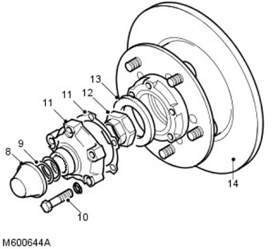
8. Remove the dust cap.
9. Remove the snap ring and adjusting shim(s) from the axle shaft.
10. Unscrew and discard the 5 bolts securing the outer hub to the hub.
11. Remove the outer hub and discard the gasket.
12. Knock off the caulking and, using a suitable socket head, loosen and discard the hub nut.
13. Remove the washer from the hub.
14. Remove the hub assembly with the brake disc and bearings.
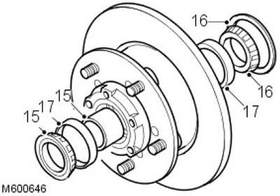
15. Remove the outer bearing and spacer from the hub.
16. Remove the seal and inner bearing from the hub.
17. Remove the inner and outer bearing rings from the hub.
Installation
1. Clean the hub and bearing areas.
2. Install the inner and outer bearing rings onto the hub.
3. Pack the inner bearing with grease and install it on the hub.
4. Install the new seal flush with the rear surface of the hub using tools LRT-54-003 and LRT-99-003.
5. Clean the splined axle shaft.
6. Pack the outer bearing with grease and install the spacer and bearing onto the hub.
7. Install the LRT-54-019 tool onto the hub nut threads on the axle housing.
8. Install the hub assembly onto the splined axle shaft and remove LRT-54-019.
9. Install the washer and new hub nut and tighten the nut to 30 Nm.
10. Rotate and push/pull the hub until the bearings are in a stable position. Tighten the hub nut to 210 Nm.
11. To check the axial clearance of the hub assembly, install a dial indicator using the LRT-99-503 bracket into the outer hub bolt hole.
12. Place the dial indicator on the contact surface of the hub nut.
13. Move the hub in and out, taking readings from the indicator.
14. If there is axial play, refer to the table for the correct spacer if necessary and replace the spacer.
| Axial clearance (mm) | Spacer size (mm) | Color code |
| 0,00 | 15,5 | Purple |
| 0,025 | 15,4 | Yellow |
| 0,050 | 15,4 | Yellow |
| 0,075 | 15,4 | Yellow |
| 0,10 | 15,3 | Red |
| 0,125 | 15,3 | Red |
| 0,150 | 15,3 | Red |
| 0,175 | 15,2 | Blue |
| 0,200 | 15,2 | Blue |
| 0,225 | 15,2 | Blue |
| 0,250 | 15,2 | Blue |
| 0,275 | 15,1 | Green |
| 0,300 | 15,1 | Green |
| 0,325 | 15,1 | Green |
| 0,350 | 15,1 | Green |
| 0,375 | 15,0 | Black |
| 0,400 | 15,0 | Black |
| 0,425 | 15,0 | Black |
| 0,450 | 15,0 | Black |
| 0,475 | 14,9 | White |
| 0,500 | 14,9 | White |
| 0,525 | 14,9 | White |
| 0,550 | 14,9 | White |
15. When there is no axial clearance, remove the dial indicator and support bracket.
16. Secure the hub nut with a caulking pin.
17. Clean the hub and axle shaft surfaces.
18. Install a new outer hub gasket.
19. Install the outer hub onto the hub and tighten the new bolts to 65 Nm.
20. Install the original adjusting shim(s) onto the axle shaft and secure with the snap ring.
21. Install the brake caliper on the hub, check the position of the fastening elements, screw in the bolts and tighten to 82 Nm.
22. Remove the plugs from the brake pipe connections.
23. Connect the brake line to the hose and tighten the connection.
CAUTION: Use two wrenches when loosening or tightening connections.
24. Remove the clamp from the brake hose.
25. Remove air from the brake system.
For more information, refer to the chapter: Bleeding the Brake System (206-00 Brake System - General Information, General Procedures).
26. Install the wheel, remove the supports from under the car and tighten the wheel nuts to 130 Nm.
27. Depress the brake pedal to position the brake pads before starting to move the vehicle.
Comments on this article