Torque Specifications
| Description | Nm | lb-ft |
| Air cooler bolts | 10 | 7 |
| Air intake resonator | 10 | 7 |
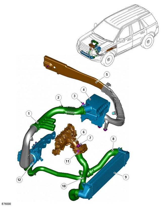
| Pos. | spare part no | Name |
| 1 | - | Duct for clean air |
| 2 | - | Crankcase ventilation connection |
| 3 | - | Mass air flow sensor (MAF) |
| 4 | - | Air filter housing |
| 5 | - | Dirty air intake duct |
| 6 | - | Electronic throttle and intake manifold assembly |
| 7 | - | Manifold absolute pressure sensor (MAP) |
| 8 | - | Hose from turbocharger to charge air cooler |
| 9 | - | charge air cooler |
| 10 | - | Hose from charge air cooler to electronic throttle (3-section) |
| 11 | - | Air intake temperature sensor (IAT) |
| 12 | - | Turbocharger and exhaust manifold |
The air intake system of the TD4 engine delivers pressurized filtered air to the engine cylinders, which contributes to the complete combustion of the injected fuel in all engine operating conditions.
The dirty air inlet is located behind the left front fender and is connected to the air filter housing. Air is drawn into the intake duct and passes through a replaceable paper filter element located in the air filter housing. The filtered air is directed through a clean air duct to the compressor side of the turbocharger.
The clean air duct has quarter-wave resonators and a connection to the crankcase ventilation system. Quarter-wave resonators reduce NVH (noise, vibration and harshness), that accompany the passage of air through the duct. Connection to the crankcase ventilation system allows environmentally harmful gases and vapors to be sucked from the engine crankcase into a clean air duct. Gases and vapors mix with filtered air and burn in the cylinders.
The turbocharger compresses and directs the pressurized hot incoming air through a large-diameter connecting hose to the charge air cooler. The air passes through the charge air cooler, where it is cooled to increase the density of the air. On the exhaust side of the aftercooler, dense cold air enters through a large gauge connecting hose to the electronic throttle and into the intake manifold, where it is then distributed through the intake manifold ports to the engine cylinders.
Exhaust gases passing through the exhaust gas recirculation system (EGR), are also sent to the air intake system to reduce the emission of nitrogen oxides (NOX). The pipeline connects the EGR valve located on the right side of the engine to the intake manifold located on the left side of the engine. The supply of exhaust gases to the intake manifold is controlled by the engine control module (ECM) under certain engine operating conditions. For more information, see the chapter: Emissions reduction (303-08B Emission Control - 2.2L Duratorq - Td4, Description and Function).
Strategically located electronic sensors around the air intake system continuously provide IAT, MAF and MAP information to the ECM. The ECM processes and uses this information to adjust engine performance based on current operating conditions and driver commands. For more information see the chapter: Electronic Engine Controls - 2.2L Diesel (303-14 Electronic Engine Controls - 2.2L Diesel, Description and function).
Comments on this article