Contents: Dismantling ⇩ Assembly ⇩
Do not bleed the air suspension system until the vehicle has been raised.
Dismantling
1. Remove the exhaust system.
EXHAUST MANIFOLD AND EXHAUST SYSTEM: Td6 engine, REPAIR WORK, Exhaust system and suspension of system components.
2. Raise the rear of the vehicle and install stands.
CAUTION: Do not work under a vehicle supported solely by a jack or lift. Always support the vehicle with safety stands.
3. Remove the wheel.
4. Bleed the air from the rear air suspension circuit.
REAR SUSPENSION, ADJUSTMENTS, Air suspension - releasing air and filling the system with air.
The original text was published on the website (www.LRman.ru)
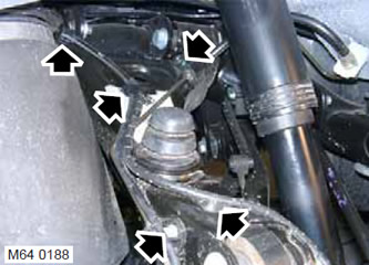
5. Disconnect the wheel speed sensor wiring from the upper control arm.
6. Remove the 2 Allen screws securing the brake hose.
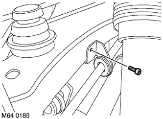
7. Remove the Allen screw securing the parking brake cable bracket.
8. Place a jack as a support under the lower suspension arm.
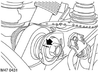
9. Mark the location of the eccentric relative to the upper arm.
10. Remove and discard the nut and bolt that secure the hub to the upper control arm. Disconnect the hub from the control arm.
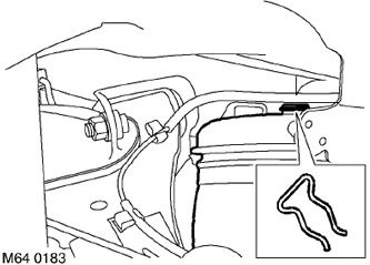
11. Remove the clamp from the upper support of the pneumatic element.
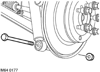
12. Unscrew the bolt securing the shock absorber to the lower arm.
13. Disconnect the shock absorber from the lower arm.
14. Support the subframe assembly with a jack.
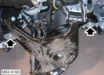
15. Unscrew the 2 bolts securing the subframe to the body.
16. Lower the subframe approximately 75 mm to provide access to the upper arm-to-subframe mounting bolts.
17. Remove the washers located on top of all the rubber bushings on the subframe.
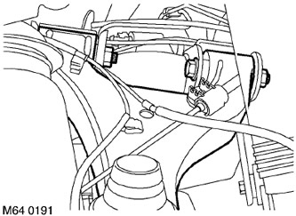
18. Unscrew the 2 upper arm mounting bolts.
19. Remove the upper arm.
Assembly
1. Clean the areas where the upper arm bushings are located from dirt.
2. Install the upper arm and tighten the bolts, but do not tighten them completely yet.
CAUTION: Nuts and bolts should be tightened with the vehicle body in its normal position.
3. Align the shock absorber with the lower arm, install the mounting bolt and tighten it to 110 N·m (81 lb ft).
4. Tighten the upper control arm-to-subframe bolts to 165 N·m (121 lb ft).
5. Install the washers on the subframe bushings.
6. Raise the subframe, install the subframe-to-body bolts and tighten them to 165 N·m (122 lb ft).
7. Pressurize the circuit to secure the upper support of the air element. Install the clamp.
8. Align the hub with the upper arm and install a new bolt. Install the eccentric according to the mark made earlier and tighten the bolt slightly.
9. Position the parking brake cable bracket to the upper control arm and tighten the Allen screw to 5 N·m (3.7 lb ft).
10. Install the Allen screws securing the brake hose to the upper control arm and tighten them to 5 N·m (3.7 lb ft).
11. Secure the wheel speed sensor wiring.
12. Bring the pressure in the air suspension system to the nominal value.
REAR SUSPENSION, ADJUSTMENTS, Air suspension, releasing air and filling the system with air.
13. Reinstall the wheel and tighten the nuts to 140 N·m (103 lb ft).
14. Lower the vehicle.
15. Reinstall the exhaust system.
EXHAUST MANIFOLD AND EXHAUST SYSTEM: Td6 engine, REPAIR WORK, Exhaust system and suspension of system components.
16. Check the wheel alignment angles.
17. Tighten the upper control arm-to-hub bolt to 165 N·m (121 lb ft).
Comments on this article