GENERAL INFORMATION, Precautions when working with electrical equipment.
Dismantling
1. Move the driver's seat to its rearmost position for easier access.
2. Remove the lower board of the control panel from the driver's side.
VEHICLE INTERIOR PARTS, REPAIR WORKS, Control panel lower shield - driver's side.
3. Raise the hood and use the service locks to secure it in a vertical position.
4. If the steering wheel is not locked, turn it to get better access to the upper steering shaft mounting screw.
5. Disconnect the negative plug from the storage battery.
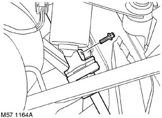
6. Working from the engine compartment, remove and discard the top screw of the steering shaft coupling.
7. Remove the steering shaft coupling assembly.
RETAINING SYSTEMS FOR DRIVER AND PASSENGERS, REPAIR WORK, Rotary Current Collector.
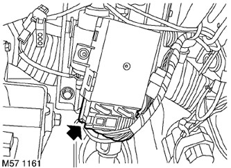
8. Only for car models with manual steering wheel adjustment. Disconnect the connector block from the control module on the steering column.
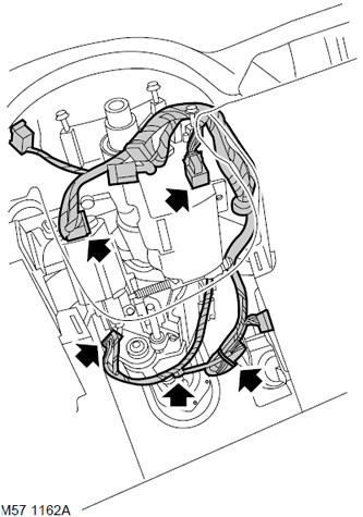
9. Disconnect blocks of sockets of mechanisms of adjustment of position and blocking of a steering wheel.
10. Remove the cable clamps and disconnect the steering angle sensor connector block.
Protect the front of the cowl next to the steering column opening
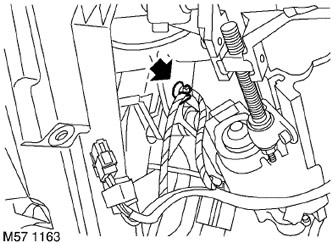
11. Release the lighting wiring harness from the retainer on the steering column frame.
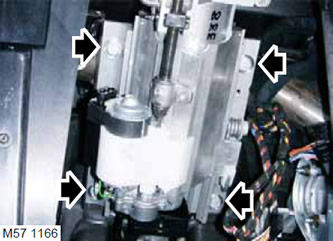
12. Turn out 4 screws of fastening of a steering column, carefully separate a steering shaft from a coupling and, together with the assistant, remove a steering column in gathering from the car.
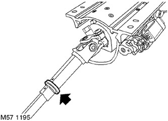
13. Check that the nylon O-ring is on the steering shaft. If the o-ring is missing, remove it from the steering column housing and put it on the free end of the steering shaft.
NOTE: Do not further disassemble if a component is being removed only for ease of access.
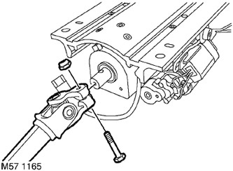
14. Remove a bolt with a nut from a place of fastening of the hinge of the lower steering shaft, remove the lower steering shaft.
15. Only for car models with manual steering wheel adjustment. Remove the 2 screws from the steering column control module and remove the module from the steering column.
Assembly
1. Only for car models with manual steering wheel adjustment. Install the control module to the steering column and tighten the mounting screws.
2. Attach the hinge of the bottom steering shaft to a steering column, establish a bolt with a nut and tighten them with the moment of 25 Н·м.
3. Apply grease to the nylon steering column O-ring.
FILLING CAPACITIES, APPLIED OPERATING LIQUIDS, OILS AND SEALANTS, Refueling tanks.
4. Carefully install the steering column assembly to the vehicle. Together with an assistant, align the steering column with the steering shaft clutch as follows. so that the groove on the steering shaft aligns with the screw hole in the steering column.
5. Install the clutch screw to ensure the correct relative position of the steering shaft.
6. Make sure the nylon o-ring is aligned with the groove in the steering column cover.
7. Install and tighten by hand the screws securing the steering column to the body panel.
8. Having ensured that the mounting spikes of the body panel coincide with the steering column, tighten the fastening screws with a torque of 25 Nm.
9. From the engine compartment, tighten the steering shaft coupling screw with a torque of 25 Nm.
10. Establish a clamp of a plait of wires of lighting and fix a plait of wires on a steering column.
11. Connect the block to the steering angle sensor connector and secure the wiring harness with the clamp.
12. Attach blocks of sockets of mechanisms of adjustment of position and blocking of a steering wheel.
13. Only for car models with manual steering wheel adjustment. Connect the connector block to the control module on the steering column.
14. Install the steering shaft clutch assembly.
RETAINING SYSTEMS FOR DRIVER AND PASSENGERS, REPAIR WORK, Rotary Current Collector.
15. Establish into place the lower board of the control panel from outside the driver.
VEHICLE INTERIOR PARTS, REPAIR WORKS, Control panel lower shield - driver's side.
16. Attach the negative plug to the storage battery.
17. Connect the gas-filled hood struts to the car body.
18. Check the operation of the drives of the tilt and extension mechanisms of the steering column and the steering wheel lock.
19. Initialization of a new steering angle sensor must be done using the Testbook/r4 diagnostic tool. The initialization procedure can be found by selecting the following icons in Testbook/r4.
- System Diagnostics
- ABS
- Vehicle maintenance
Comments on this article