Before disconnecting the battery, make sure that all the requirements and conditions contained in the section on disconnecting the battery are met.
GENERAL INFORMATION, Precautions when working with electrical equipment.
Camber check
1. Check for wear and play in the steering joints, suspension joints and wheel bearings. Repair or adjust if necessary.
2. Make sure the tire pressure is correct and the body height is correct.
3. Roll the car forward - backward to relieve stress in the suspension and steering elements.
4. Make sure the wheel alignment equipment is properly calibrated.
NOTE: Use only Land Rover approved four wheel alignment equipment.
Adjustment
1. Disconnect the negative plug from the storage battery.
2. Using the readings of the equipment, adjust the installation angles in accordance with the regulations.
TECHNICAL DATA, Steering.
3. Adjusting the angles of the rear wheels.
4. Camber adjustment:
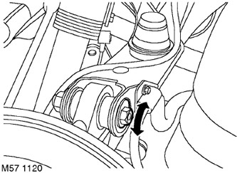
5. Loosen the upper ball joint nut approximately 3/4 turn.
6. Turning the eccentric, set the value of the camber angle in accordance with the normalized value.
7. Tighten the upper ball joint nut to 165 Nm.
8. Repeat the operation for the wheel on the other side.
9. Adjusting the convergence of the rear wheels:
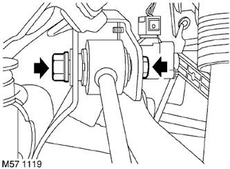
10. Loosen the tie rod mounting nut about 3/4 turn.
11. Turning the eccentric, set the value of the angle of convergence in accordance with the normalized value.
12. Tighten the upper ball joint nut to 165 Nm.
13. Repeat the operation for the wheel on the other side.
14. Adjusting the angles of the front wheels.
15. Camber adjustment:
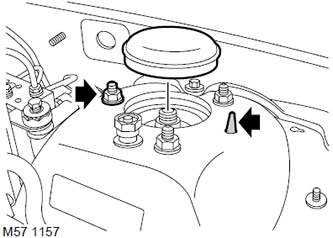
16. Remove the shock absorber mounting top cover.
17. Remove the setting pin.
18. Loosen the upper shock absorber mounting nut.
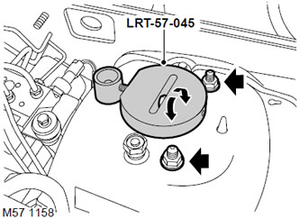
19. Install tool LRT-57-045 on the shock absorber upper support.
20. Loosen the remaining nuts of the upper shock absorber support.
21. Set the desired camber by turning the LRT-57-045 nut.
22. Tighten the shock absorber top nut to 56 Nm.
23. Repeat the operation for the wheel of the other side.
24. Adjusting the convergence of the front wheels.
25. Set the front wheels to the straight-ahead position and check that the steering shaft gear position marks match.
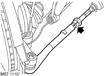
26. Mark the position of each tie rod end relative to the tie rod.

27. Loosen the locknuts securing the tie rod ends.
28. Adjust the toe-in by turning the tie rod, acting on the hexagon of the tie rod. Do not allow the handpiece body to rotate and the protective sheath to twist.
CAUTION: The right and left tie rods must turn at the same angle.
29. Check up again a convergence of forward wheels.
30. Tighten the steering rod locknuts with a tightening torque of 55 Nm.
31. Connect the negative terminal to the battery.
Comments on this article