GENERAL INFORMATION, Precautions when working with electrical equipment.
Dismantling
1. Put the car on a lift.
2. Disconnect the negative plug from the storage battery.
3. Raise the front of the vehicle and jack it up.
4. Remove the front wheels.
5. Remove the protective shield.
EXTERIOR PARTS, REPAIR WORKS, Engine protection - front.
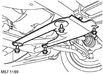
6. Turn out 4 screws of fastening of the bottom aerodynamic panel and remove the panel.
7. Remove the left drive shaft.
DRIVE SHAFTS, REPAIR WORKS, Drive shaft - front - left.
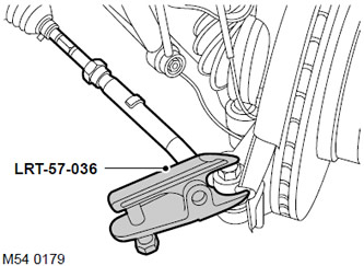
8. Remove and discard the left ball stud to steering knuckle nut.
9. Screw an M14 nut onto the end of the ball stud, flush with the threaded end of the stud.
10. Using tool LRT-57-036, separate the ball pin from the steering knuckle. Remove the M14 nut and remove the ball pin from the steering knuckle.
CAUTION: Check that the ball stud boot is not damaged. A damaged protective boot will cause failure of the ball joint.
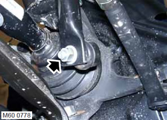
11. Remove the two nuts securing the rods to the anti-roll bar and disconnect the rods.
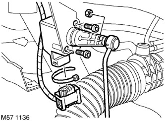
12. Mark the position of the clips and remove the clips securing the left body position sensor cable to the vehicle's subframe.
13. Remove block from an electric socket of the gauge.
14. Turn out 2 screws of fastening of the gauge of provision of a body and remove the gauge.
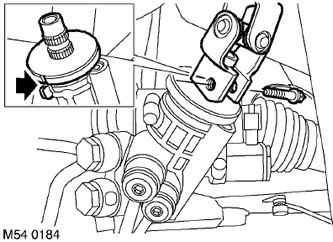
15. Turn out the screw of the bottom hinge of a steering column.
16. Turn the steering wheel to the straight ahead position, align the marks on the steering gear shaft and remove the ignition key.
CAUTION: Do not turn the steering wheel when the intermediate shaft or universal joint is disconnected as this will damage the rotating current collector and steering wheel switches.
17. Disconnect the steering column from the gear shaft.
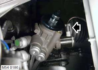
18. Remove the connector block of the sensor of the angle of rotation of the gear shaft of the steering gear.
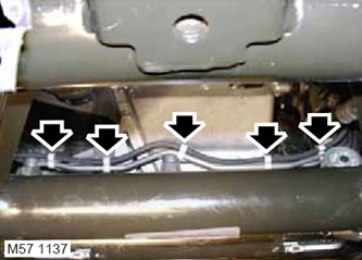
19. Disengage the 5 clips securing the vacuum hose to the steering gear housing assembly.
20. Install a container to collect the flowing fluid.
CAUTION: Before disconnecting or removing steering components, make sure that the surfaces adjacent to the connection points are free of dirt. Install plugs in fittings and piping to keep dirt out of the system.
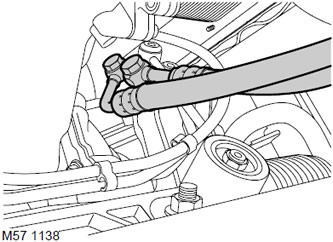
21. Mark position of unions of pressure head and drain pipelines on the body of the executive cylinder, turn out bolts of unions and remove sealing rings.
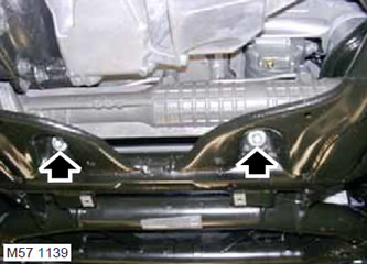
22. Remove 2 bolts and 2 nuts securing rail assembly, discard bolts and nuts.
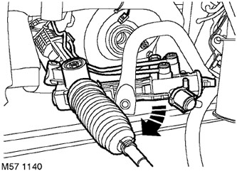
23. Together with an assistant, carefully release the steering assembly by turning it. Remove the steering gear assembly from the left side of the vehicle.
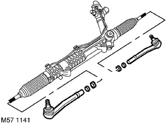
24. Loosen the locknuts securing the tie rod ends.
25. Remove the tie rod ends, remembering the number of turns on the thread, so as not to be mistaken during assembly.
26. Remove and discard retaining rings.
27. Remove locknuts.
Assembly
1. Screw the lock nuts onto the ends of the tie rods.
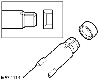
2. Fit the circlips on the ends of the tie rods so that the conical part of the ring faces the conical band of the tie rod.
3. Screw the tie rod ends onto the tie rods by turning them the number of revolutions recorded during removal.
4. Install the steering gear assembly and tighten the new bolts and nuts with a tightening torque of 100 N·m, then tighten the nuts by 90°.
5. Fix the vacuum pipeline on the case of the steering mechanism.
6. Clean the pipe fittings and connections from dirt.
7. Install new O-rings and connect the pipe fittings by tightening the M16 screw with a torque of 40 Nm, and the M14 screw with a torque of 36 Nm.
8. Connect block to a socket of the gauge of an angle of rotation of a steering shaft.
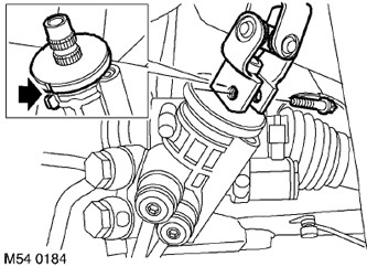
9. Check the alignment of the marks on the steering gear shaft and attach the steering shaft. Install the steering column lower pivot screw and tighten to 24 Nm.
10. Install the body position sensor on the subframe and tighten the mounting bolts with a torque of 2.5 Nm.
CAUTION: Make sure the sensor arm is facing out.
11. Attach a block of an electric socket of the gauge.
12. Route the sensor cable and secure it with the clamps in the original position. Check that the cable is not under tension.
13. Attach the anti-roll bar rods, screw the nuts and tighten them with a torque of 100 Nm.
14. Clear conic surfaces of spherical pins and sockets of rotary fists from dirt.
15. Connect fingers of spherical hinges with rotary fists, establish new nuts and tighten them with the moment of 80 Нм.
16. Reinstall the left drive shaft.
DRIVE SHAFTS, REPAIR WORKS, Drive shaft - front - left.
17. Reinstall the lower aerodynamic panel and tighten the bolts to 45 Nm.
18. Replace the protective shield.
EXTERIOR PARTS, REPAIR WORKS, Engine protection - front.
19. Lower the lift.
20. Reinstall the wheels and tighten the nuts to 140 Nm.
21. Remove props and lower the car.
22. Connect the negative terminal to the battery.
23. Remove air and add working fluid to the hydraulic booster reservoir.
STEERING, ADJUSTMENTS, Power Steering (PAS) - removal of air.
24. Check and, if necessary, adjust the angles of the front wheels.
STEERING, ADJUSTMENTS, Front wheel alignment - check and adjustment.
Comments on this article