car logo Ford
car logo Volkswagen
car logo BMW
car logo Opel
car logo Audi
car logo Toyota
car logo Peugeot
English Русский
Български
Беларускі
Український
Српски
Hrvatski
Română
Polski
Slovenský
Magyar


Main
Freelander
Discovery
Range Rover
Defender
Contacts
Articles

Brake pedal assembly (Range Rover 3)

 
  • Main
  • Range Rover
  • Range Rover 3
  • Chassis
  • Brake system
  • Brake pedal assembly
 
        0  
Contents: Dismantling ⇩ Assembly ⇩

Dismantling


1. Remove the panel covering the brake pedal assembly.

CAR INTERIOR PARTS, REPAIR WORK, Lower control panel shield - passenger side.


2. Remove the protective shield.

CAR INTERIOR PARTS, REPAIR WORK, Lower control panel casing.
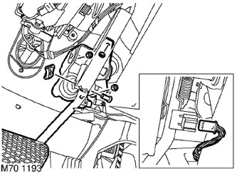

3. Disconnect the brake pedal position sensor cable connector from the pedal assembly.


3. Disconnect the brake pedal position sensor cable connector from the pedal assembly.

4. Remove the cotter pin and remove the pin connecting the vacuum booster pushrod to the brake pedal.

5. Remove and discard the three nuts securing the brake pedal assembly to the body panel.

6. Separate the brake pedal assembly and remove it from the vehicle.

NOTE: Do not perform further disassembly if the unit is removed only for ease of access.


7. Loosen and remove the brake pedal position sensor from its socket.

8. Remove the sensor socket from the brake pedal bracket.

9. Remove the brake pedal return spring.

10. Loosen the two nuts and remove the two bolts securing the return spring bracket to the brake pedal assembly. Remove the spring bracket.

Assembly


1. Install the return spring bracket onto the brake pedal assembly, insert the mounting bolts, screw the nuts onto them and tighten them to a torque of 10 N·m.


2. Connect the return spring to the pedal bracket and install the pedal position sensor on it.

3. Install the pedal assembly onto the body panel, install new nuts and tighten them to 26 N·m.

The article was copied from the website [www.lrman.ru]

CAUTION: The nuts connecting the vacuum booster to the pedal bracket should be re-tightened after 30 minutes.


4. Install the brake pedal position sensor into the socket, connect the wire connector to its connector and secure it in the socket.

5. Connect the pusher to the pedal, insert the pin and install the cotter pin into its hole.

6. Make sure the sensor contacts the pedal protrusion when the pedal is in the raised position.

7. Replace the protective shield.

CAR INTERIOR PARTS, REPAIR WORK, Lower control panel casing.


8. Reinstall the brake pedal assembly cover panel.

CAR INTERIOR PARTS, REPAIR WORK, Lower control panel shield - passenger side.


This article is available at russian, bulgarian, belarusian, ukrainian, serbian, croatian, romanian, polish, slovak, hungarian
Article review: Platon Fedorov


Previous articles
Checking the wear and runout of the front brake disc
Checking the wear and runout of the rear brake disc
Bleeding the brake system
Adjusting the parking brake
Front brake disc
Rear brake disc
Pre-pressure pump
Brake system reservoir

Current article
Brake pedal assembly

Next articles
Parking brake lever assembly
Parking brake cables
Parking brake indicator switch
Front brake pads
Rear brake pads
Front brake pad wear sensor
Rear brake pad wear sensor
Rear drum brake pads


Similar articles from Land Rover repair manuals:
• Brake pedal control switch Freelander 2 (2006-2014)
• Brake fluid — replacement Freelander 1 (1997-2006)
• Brake pedal and pedal bracket (manual transmission) Discovery 3 (2004-2009)
• Brake pedal switch Discovery 1 (1989-1998)
• Brake pedal and pedal bracket Defender 2007+ (2007-2016)

Comments on this article


No comments yet


How much will 48 + 22 =


Range Rover 3 
  • General information
  • Using the manual
  • Precautionary measures
  • Repair techniques
  • Identification codes
  • Specifications
  • Tightening torques
  • Materials
  • Maintenance
  • Power unit
  • Diesel engine TD6
  • Petrol engine V8
  • Emission reduction TD6
  • Emission reduction V8
  • Engine management TD6
  • Engine management V8
  • Fuel supply TD6 engine
  • Fuel supply V8 engine
  • Engine cooling TD6
  • Engine cooling V8
  • Exhaust system TD6
  • Exhaust system V8
  • Transfer case
  • Automatic gearbox GM-5L40-E
  • Automatic gearbox ZF 5HP24
  • Chassis
  • Drive shafts
  • Main gear
  • Front axle gear
  • Steering
  • Front suspension
  • Rear suspension
  • Brake system
  • Body and coating
  • Passenger safety
  • Doors and windows
  • Exterior details
  • Interior details
  • Glasses
  • Seats
  • Sunroof
  • Body geometry
  • Body repair
  • Corrosion protection
  • Electrical equipment
  • Heating and ventilation
  • Conditioning
  • Windshield wipers and washers
  • Starting and charging system
  • Lighting and headlights
  • Electronic blocks
  • Entertainment system
  • Wiring harnesses


LRman.ru © 2013-2026 | Mobile version | Free Lander | Discovery | Range Rover | Defender | Contacts | | Sitemap |
Car repair and service instructions Land Rover: Freelander, Discovery, Range Rover, Defender
We use cookies to make pages load faster and provide a more user-friendly experience 🍪