Dismantling
1. Raise the front of the car.
WARNING: Do not work under a vehicle raised only on a jack or lift. Always install safety props.
2. Remove the wheel.
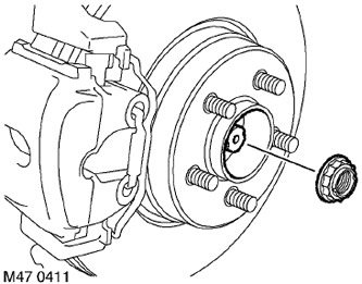
3. Remove the hub bearing nut cotter pin.
4. Have a partner press the brake pedal, unscrew the bearing nut and discard it.
5. Remove the brake disc.
BRAKING SYSTEM, REPAIR WORKS, Brake disc - front brake mechanisms.
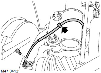
6. Release the wheel speed sensor wiring harness from the clamp.
7. Disconnect the electrical wiring from the shock absorber, remove the Allen screw and remove the wheel speed sensor from the hub.
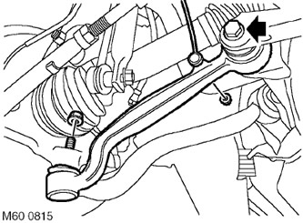
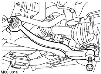
8. Turn away a nut of fastening of draft of the gauge of height of position of a body to the bottom lever and disconnect draft.
CAUTION: Use a socket wrench to prevent rotation of the ball joint.
9. Loosen the bolt securing the lower arm to the subframe by backing it out a quarter of a turn.
10. Turn away a nut of fastening of a spherical support of the lower lever to a nave.
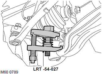
11. Using tool LRT-54-027, release the lower arm ball joint and disconnect the lower arm from the hub.
CAUTION: Check that the ball joint boot is not damaged. A damaged boot will result in hinge failure.
12. Loosen the tie rod to subframe bolt by backing it out a quarter of a turn.
13. Turn away a nut of fastening of cross steering draft to a spherical support.
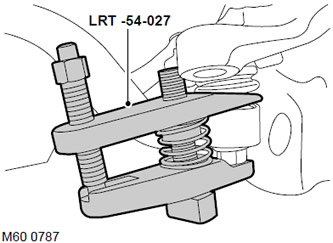
14. Using tool LRT-54-027, disconnect the tie rod from the ball joint.
CAUTION: Check that the ball joint boot is not damaged. A damaged boot will result in hinge failure.
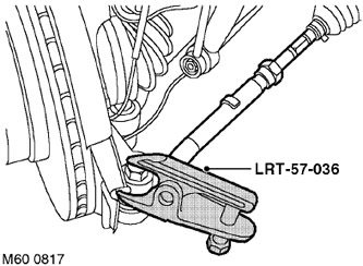
15. Remove and discard the tie rod ball stud to steering knuckle nut.
16. Screw an M14 nut onto the end of the ball stud, flush with the end of the threaded part of the stud.
17. Using tool LRT-57-036, separate the ball pin from the steering knuckle. Remove the M14 nut and remove the ball pin from the steering knuckle.
CAUTION: Check that the ball joint boot is not damaged. A damaged boot will result in hinge failure.
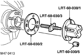
18. Screw the central screw LRT-60-030/3 onto the tool LRT-60-030/1 and install it on the hub together with the washer LRT-60-030/2. Fasten the tool with nuts LRT-60-030/5.
19. Turn in the center screw to force the drive shaft out of the hub.
20. Remove the tool.
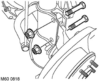
21. Turn away 2 nuts from bolts of fastening of a nave to the shock-absorber.
22. Remove the hub assembly.
Assembly
1. Clean the mating surfaces of the hub and shock absorber from dirt.
2. Clean the splines of the drive shaft and hub from dirt.
3. Lightly grease the splined surfaces.
4. Install the hub assembly and insert the top bolt. Insert the drive shaft into the hub, align the hub and insert the bottom bolt. Attach the hub to the shock absorber by tightening the nuts to 250 Nm (184 lb ft).
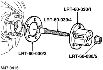
5. Install tool LRT-60-030/4 on the drive shaft.
6. Fit tool LRT-60-030/1 together with washer LRT-60-030/2 and fix the tool with nuts LRT-60-030/5.
7. Screw the nut onto the tool LRT-60-030/4 and tighten it to fully insert the drive shaft into the hub flange.
8. Remove the tool.
9. Clean the tapered surfaces of the ball pin and steering knuckle socket from dirt.
10. Connect the ball pin to the steering knuckle, install a new nut and tighten it with a torque of 80 Nm (59 lb ft).
11. Connect the tie rod to the ball joint and tighten the nut with a torque of 80 Nm (59 lb ft).
12. Connect the ball joint of the lower arm to the hub and tighten the nut with a torque of 80 Nm (59 lb ft).
13. Screw the lower arm and tie rod bolts to the subframe, but do not tighten them yet.
14. Connect the lower arm to the ball joint and tighten the nut with a torque of 8 Nm (6 lb ft).
CAUTION: Make sure the sensor arm is facing out.
15. Clean the surface of the wheel speed sensor, apply an anti-stick lubricant, and attach it to the hub.
FILLING CAPACITIES, USED OPERATING LIQUIDS, OILS AND SEALANTS, Lubrication system.
16. Install the Allen type screw securing the wheel speed sensor and tighten it to a torque of 8 Nm (6 lb ft).
17. Attach the sensor wiring to the shock absorber.
18. Install the front wheel brake disc.
BRAKING SYSTEM, Brake disc - front brakes, Brake disc - front brakes.
19. Install a new wheel bearing nut and tighten to 420 Nm (311 lb ft).
20. Snap the nut onto the drive shaft.
21. Reinstall the wheel and tighten the nuts to 140 Nm (103 lb ft).
22. Remove props and lower the car.
23. Tighten the bolt securing the lower arm to the subframe with a torque of 165 Nm (121 lb ft) and turn it 90°.
24. Tighten the tie rod bolt to the subframe with a torque of 165 Nm (121 lb ft) and turn it 90°.
25. Check the angles of the front wheels.
Comments on this article