car logo Ford
car logo Volkswagen
car logo BMW
car logo Opel
car logo Audi
car logo Toyota
car logo Peugeot
English Русский
Български
Беларускі
Український
Српски
Hrvatski
Română
Polski
Slovenský
Magyar


Main
Freelander
Discovery
Range Rover
Defender
Contacts
Articles

Transverse steering rod (Range Rover 3)

 
  • Main
  • Range Rover
  • Range Rover 3
  • Chassis
  • Front suspension
  • Transverse steering rod
 
        0  
Contents: Dismantling ⇩ Assembly ⇩

Dismantling


1. Raise the front of the vehicle.

CAUTION: Do not work under a vehicle supported solely by a jack or lift. Always support the vehicle with safety stands.


2. Remove the wheel.
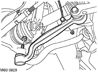
3. Loosen the nut securing the body height sensor rod to the lower arm and disconnect the rod.


3. Loosen the nut securing the body height sensor rod to the lower arm and disconnect the rod.

4. Loosen the bolt securing the lower arm to the subframe by turning it a quarter of a turn.

5. Unscrew the nut securing the ball joint to the lower arm.
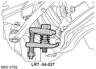
6. Using the LRT-54-027 tool, release the lower arm ball joint and disconnect the lower arm from…


6. Using the LRT-54-027 tool, release the lower arm ball joint and disconnect the lower arm from the hub.

CAUTION: Make sure that the ball joint protective boot is not damaged. A damaged boot will cause the joint to fail.
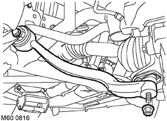


7. Loosen the bolt securing the tie rod to the subframe by turning it a quarter of a turn.


7. Loosen the bolt securing the tie rod to the subframe by turning it a quarter of a turn.

8. Unscrew the nut securing the transverse steering rod to the ball joint.
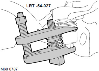
9. Using the LRT-54-027 tool, disconnect the tie rod from the ball joint.


9. Using the LRT-54-027 tool, disconnect the tie rod from the ball joint.

10. Unscrew the bolt securing the transverse steering rod to the subframe. Discard the bolt.

11. Remove the tie rod.

Assembly


1. Clean any dirt from the conical surfaces of the ball pin and the steering knuckle socket.

2. Install the tie rod and install the new bolt without tightening it completely yet.

CAUTION: Nuts and bolts must be tightened after the vehicle is installed on the wheels.


3. Connect the tie rod to the ball joint and tighten the nut to 80 N·m (59 lb ft).


CAUTION: Make sure that the ball joint protective boot is not damaged. A damaged boot will cause the joint to fail.


4. Connect the lower arm ball joint to the hub and tighten the nut to 80 N·m (59 lb ft).

5. Replace the lower arm-to-subframe mounting bolt, but do not tighten it completely yet.

6. Reinstall the wheels and tighten the nuts to 140 N·m (103 lb ft).

7. Remove the supports and lower the vehicle.

8. Tighten the lower arm-to-subframe bolt to 165 N·m (121 lb ft) and turn it through 90°.

9. Tighten the tie rod to subframe mounting bolt to 165 N·m (121 lb ft) and turn it through an additional 90°.

10. Check the front wheel alignment angles.


This article is available at russian, bulgarian, belarusian, ukrainian, serbian, croatian, romanian, polish, slovak, hungarian
Article review: Platon Fedorov


Previous articles
Bleeding and filling the air suspension system with air
Setting up the air suspension system
Anti-roll bar
Anti-roll bar struts
Lower control arm ball joints
Pneumatic elastic element assembly
Wheel hub
Wheel hub bearing

Current article
Transverse steering rod

Next articles
Tie rod bushings
Receiver
Electronic control unit for air suspension
Compressor unit
Pressure regulator unit
Bypass valve


Similar articles from Land Rover repair manuals:
• Steering Angle Sensor Module (SASM) fault code Freelander 2 (2006-2014)
• Power Steering Fluid Level (PAS) Freelander 1 (1997-2006)
• Transverse steering rod Discovery 3 (2004-2009)
• Transverse steering rod Discovery 1 (1989-1998)
• Steering Specifications Defender 2007+ (2007-2016)

Comments on this article


No comments yet


How much will 28 + 48 =


Range Rover 3 
  • General information
  • Using the manual
  • Precautionary measures
  • Repair techniques
  • Identification codes
  • Specifications
  • Tightening torques
  • Materials
  • Maintenance
  • Power unit
  • Diesel engine TD6
  • Petrol engine V8
  • Emission reduction TD6
  • Emission reduction V8
  • Engine management TD6
  • Engine management V8
  • Fuel supply TD6 engine
  • Fuel supply V8 engine
  • Engine cooling TD6
  • Engine cooling V8
  • Exhaust system TD6
  • Exhaust system V8
  • Transfer case
  • Automatic gearbox GM-5L40-E
  • Automatic gearbox ZF 5HP24
  • Chassis
  • Drive shafts
  • Main gear
  • Front axle gear
  • Steering
  • Front suspension
  • Rear suspension
  • Brake system
  • Body and coating
  • Passenger safety
  • Doors and windows
  • Exterior details
  • Interior details
  • Glasses
  • Seats
  • Sunroof
  • Body geometry
  • Body repair
  • Corrosion protection
  • Electrical equipment
  • Heating and ventilation
  • Conditioning
  • Windshield wipers and washers
  • Starting and charging system
  • Lighting and headlights
  • Electronic blocks
  • Entertainment system
  • Wiring harnesses


LRman.ru © 2013-2026 | Mobile version | Free Lander | Discovery | Range Rover | Defender | Contacts | | Sitemap |
Car repair and service instructions Land Rover: Freelander, Discovery, Range Rover, Defender
We use cookies to make pages load faster and provide a more user-friendly experience 🍪