Contents: Dismantling ⇩ Assembly ⇩
Do not bleed the air suspension system until the vehicle has been raised.
It is not necessary to release air from the entire air suspension system; it is enough to release it only from the circuit of the replaced air element.
When disconnecting a Voss type nipple from any air suspension component, do not remove it from the air hose being disconnected. Do not remove the nipple from the air hose. When removing the nipple from the hose, there is a high probability of scratching the nipple, which may later lead to air leakage from the system.
Dismantling
1. Raise the front of the vehicle and support it with stands.
CAUTION: Do not work under a vehicle supported solely by a jack or lift. Always support the vehicle with safety stands.
2. Remove the wheel(s).
3. Release air from the replaced pneumatic element.
FRONT SUSPENSION, ADJUSTMENTS, Air suspension system - releasing air and filling the system with air.
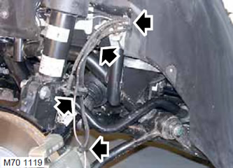
4. Disconnect the wheel speed sensor wiring and air hose from the shock absorber.
5. For left air spring only: Disconnect the electrical wire of the brake pad wear sensor from the shock absorber.
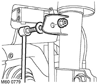
6. Loosen the nut securing the anti-roll bar to the shock absorber.
CAUTION: Use a socket wrench to prevent the ball joint from rotating.
7. Remove the stabilizer bar and washer.
CAUTION: Mark the location of the washer for subsequent installation.
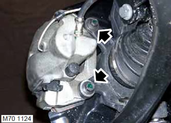
8. Unscrew the two bolts securing the brake caliper to the hub. Remove the caliper from the hub and secure it to the side.
CAUTION: Do not allow the caliper to hang by the brake hose.
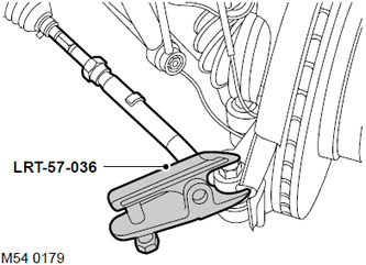
9. Loosen the nut at the end of the tie rod.
10. Screw the M14 nut onto the end of the ball joint flush with the end of the threaded part of the joint.
11. Using the LRT-57-036 tool, disconnect the ball pin from the steering knuckle. Remove the M14 nut and pull the ball pin out of the steering knuckle.
CAUTION: Make sure that the ball joint protective boot is not damaged. A damaged boot will cause the joint to fail.
12. Place a jack as a support under the lower suspension arm.
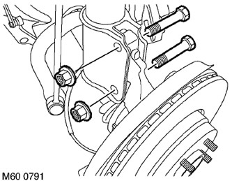
13. Unscrew the 2 nuts from the bolts securing the hub to the shock absorber.
14. Disconnect the hub from the shock absorber and lower arm and clean the shock absorber.
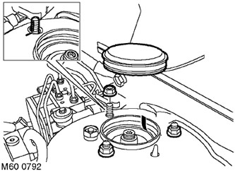
15. Remove the cover from the top support.
16. Unscrew the nut securing the air spring and shock absorber assembly, which is located on the inside, and mark the relative positions of the strut and upper support for subsequent assembly.
17. Remove the 2 remaining nuts and disconnect the air spring and shock absorber assembly, lowering it enough to allow access to the air hose fitting.
The article was taken from this resource: www.lrman.ru
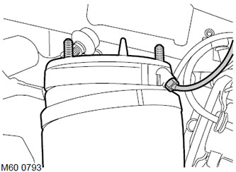
18. Disconnect the fitting from the pneumatic elastic element.
CAUTION: Always plug the fittings and holes to protect the system from dirt.
19. Remove the air spring and shock absorber assembly.
20. Remove the paper gasket from the air spring and shock absorber assembly and discard it.
Assembly
1. Clean the location of the air spring and shock absorber.
CAUTION: Inspect the air element for damage. If the air element is damaged, it must be replaced.
2. When installing a new air spring and shock absorber assembly, remove the air nipple from it.
3. Install a new paper gasket on the air spring and shock absorber assembly.
4. Install the air spring and shock absorber assembly, connect the air hose, but do not tighten the connection yet.
CAUTION: Clean the air hose connection area.
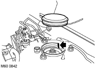
5. Attach the air spring and shock absorber assembly to the body. Install the upper mounting nuts, align the mounting pin with the mark, and finally tighten the nuts to 56 N·m (42 lb ft).
CAUTION: Ensure that the mark on the gasket is visible through the large hole drilled in the support. (see picture).
6. Place the cover on the top support.
7. Tighten the air hose fitting to 3.5 N·m (2.6 lb ft).
8. Connect the hub to the shock absorber, install the bolts and tighten them to 250 N·m (184 lb ft).
9. Clean any dirt from the conical surfaces of the ball pin and the steering knuckle socket.
10. Connect the ball stud to the steering knuckle, install a new nut and tighten it to 80 N·m (59 lb ft).
11. Clean the mating surfaces of the brake caliper and hub.
12. Install the caliper onto the hub and tighten the bolts to 110 N·m (81 lb ft).
13. Secure the brake hose and wheel speed sensor wiring to the shock absorber.
14. For left air spring only: Secure the brake pad wear sensor.
15. Install the washer, connect the stabilizer bar link, install the nut and tighten it to 100 N·m (74 lb ft).
CAUTION: The hardened washer must be installed in the same position it was in before removal.
16. Bring the pressure in the air suspension system to the nominal value.
FRONT SUSPENSION, ADJUSTMENTS, Air suspension system - releasing air and filling the system with air.
CAUTION: Before removing the support and placing the vehicle on its wheels, it is necessary to bring the pressure in the air suspension system to the nominal value.
17. Reinstall the wheel(s) and tighten the nuts to 140 N·m (103 lb ft).
18. Remove the support(s) and lower the vehicle.
19. Check the front wheel alignment angles.
Comments on this article