Contents: Removal ⇩ Installation ⇩
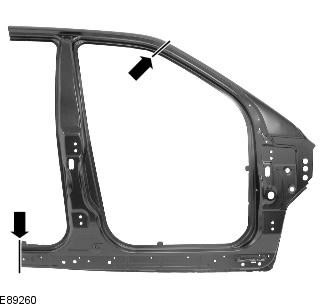
CAUTION: The front section of the side panel should be MIG welded to its reinforcement member, which contains DP600 (dual phase steel). Plug welds/MIG spot welds should not be used.
NOTE: The front section of the side panel is serviced as a separate welded panel, without the fender support bracket, which is serviced separately.
NOTE: NVH components are mounted inside this panel; they are not serviceable on the new panel. If damaged, new element(s) will be required.
Removal
1. When replacing the front section of the side panel, the following elements are removed:
- Front bumper trim
- Front wing
- Hood
- Front door
- Back door
- Instrument panel
- Windshield
- Ceiling lining
2. For additional information on this repair procedure, refer to the following sources: For additional information, refer to: Body and Frame (501-26 Body Repairs - Vehicle Specific Information and Tolerance Checks, Description and Operation) / Standard Service Station Techniques (100-00 General Information, Description and Operation).
3. Remove the hood.
4. Remove the front fender.
5. Remove the front door. For more information, refer to the chapter: Front Door (501-03 Lockable Body Parts, Removal and Installation).
Data taken from the website www.LRman.ru
6. Remove the rear door. For more information, refer to the chapter: Rear Door (501-03 Lockable Body Parts, Removal and Installation).
7. Remove the headlining. For more information, refer to the chapter: Upper Trim - Vehicles not equipped with: Tilting Sunroof (501-05 Interior Trim, Removal and Installation) / Upper Trim - Vehicles equipped with: Tilting Sunroof (501-05 Interior Trim, Removal and Installation).
8. Remove the instrument panel. For more information, refer to the chapter: Control panel - 2.2L Duratorq - Td4 (501-12 Instrument panel and console, Removal and installation).
9. Remove the windshield. For more information, refer to the chapter: Windshield (501-11 Glass, Frames and Mechanisms, Removal and Installation).
10. Remove the upper and lower door hinges from the A-pillar (four bolts).
11. Remove the upper and lower door hinges from the B-pillar (four bolts).
12. Remove the front door lock mating part from the B-pillar.
13. Remove the side curtain airbag module. For additional information, refer to: Side curtain airbag module (501-20B Supplemental Restraint System, Removal and Installation).
14. Remove the rear seat cushion. For more information, refer to the chapter: Rear Seat Cushion (501-10 Seat, Removal and Installation).
15. Remove the left and right lower trim inner panels.
16. Remove the side impact sensor from the B-pillar. For more information, refer to: Side Impact Sensor (501-20B Supplemental Restraint System, Removal and Installation).
17. Remove the front seat belt retractor. For more information, refer to the chapter: Front Seat Belt Retractor (501-20A Seat Belt System, Removal and Installation).
18. Release and set aside the front section of carpet.
19. Remove the rear section of carpet.
20. Remove the front and rear roof molding sections.
21. Remove the front wheel. For more information, refer to the chapter: Wheel and tire (204-04 Wheels and tires, Removal and installation).
22. Remove the lower trim panel outer molding.
23. Remove and set aside the insulating material located on the inner partition.
24. Release and set aside the wiring harnesses on the A-pillar, B-pillar, and lower trim panel.
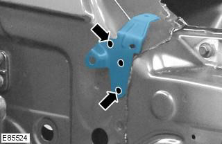
25. Remove the wing support bracket.
- Mill three spot welds. If the support is not to be reused, the top spot weld should not be removed.
- Disconnect the support from the "A" pillar.
- Keep the support if it is reused. If not, discard it.
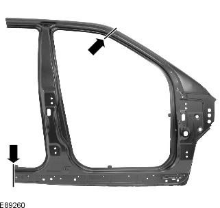
26. Cut the old panel to size on the A-pillar and lower trim panels using the new panel as a template and ensuring that the new panel overlaps the panel remaining on the vehicle.
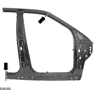
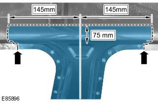
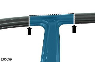
27. Cut the old panel on post 'B' as shown, following the dimensions given, to allow access to the 'B' post reinforcement.
28. Mill out the contact welding areas.
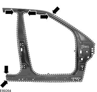
29. Disconnect the connections and remove the old panel, also releasing the NVH elements.
Installation
1. Position the new panel and lock it in position, ensuring that it overlaps the old panel remaining on the vehicle. Check the alignment. If correct, proceed to the next step. If not, make any necessary adjustments and recheck before continuing.
2. Cut new and old panels on the bottom trim panel and A-post where MIG butt joints are to be made.
3. Cut the new and old panels on the B-pillar where the MIG butt joint is to be made.
4. Remove the new panel and the remains of the old panel.
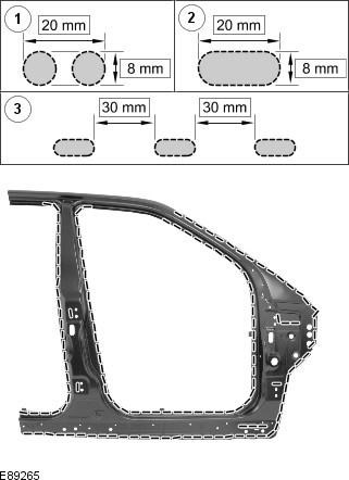
5. Cut holes in the new panel prepared for MIG soldering.
NOTE: MIG welding holes should be positioned in accordance with the intervals shown in the illustration. Where this is not possible due to dents in the panel, the hole should be made at the location of the original spot weld.
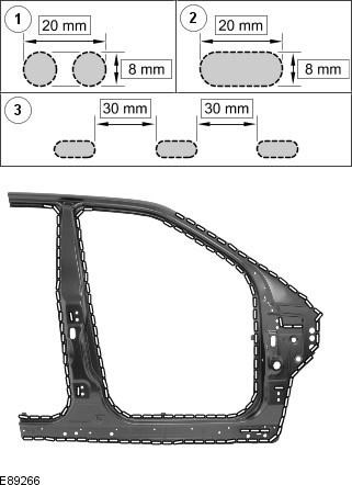
6. Prepare the mating surfaces of the old and new panels.
7. Replace NVH element(s) if necessary.
8. Apply adhesive to the NVH element on the A-pillar.
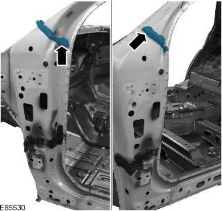
9. Apply adhesive to the NVH element on the B-pillar.
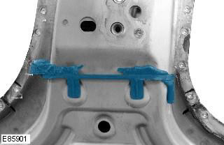
10. Apply glue to the A-pillar as shown.
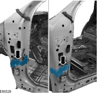
11. Place the new panel in the required location and secure it.
12. Perform tack welds for butt joints.
13. Perform through-hole MIG soldering.
14. Clean the tack welds.
15. Perform a MIG butt joint in the upper area of the "B" pillar.
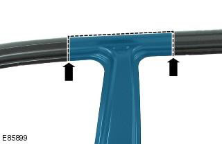
16. Make MIG butt joints on the A-pillar and the bottom trim panel.
17. Clean all welds.
18. Installation of the relevant panels and mechanical elements is carried out in the reverse order of removal.
Comments on this article