Contents: Removal ⇩ Installation ⇩
WARNING: The side panel must be soldered with MIG hard solder to its amplifier, which includes DP600 (two-phase steel). MIG electric rivet welding / spot welding should not be used.
NOTE: The side panel is serviced as a separate welded panel, serviced without the wing support bracket, which is serviced separately.
NOTE: There are NVH components attached inside this panel, they are not serviceable on the new panel. If damaged, new component(s) will be required.
Removal
1. In combination with the side panel, replaces:
- Front bumper trim
- Front wing
- Hood
- Front door
- Back door
- Rear side panel glass
- Instrument panel
- Windshield
- Ceiling upholstery
- Rear bumper trim
2. For additional information regarding this repair procedure, refer to: For additional information, refer to: Body and Frame (501-26 Body Repairs - Special Vehicle Information and Tolerance Checks, Description and Operation) / Standard Service Station Techniques (100-00 General Information, Description and Operation).
3. Remove the hood.
4. Remove the front fender.
5. Remove the front door. For more information, refer to the chapter: Front Door (501-03 Lockable Body Parts, Removal and Installation).
6. Remove the rear door. For more information, refer to the chapter: Rear Door (501-03 Lockable Body Parts, Removal and Installation).
7. Remove the headlining. For more information, refer to the chapter: Upper trim - Vehicles not equipped with: Tilting sunroof (501-05 Interior trim, Removal and Installation) / Upper trim - Vehicles equipped with: Tilting sunroof (501-05 Interior trim, Removal and Installation).
8. Remove the instrument panel. For more information, refer to the chapter: Control panel - 2.2L Duratorq - Td4 (501-12 Instrument panel and console, Removal and installation).
9. Remove the windshield. For more information, refer to the chapter: Windshield (501-11 Glass, Frames and Mechanisms, Removal and Installation).
10. Remove the rear side window glass. For more information, refer to the chapter: Rear side window glass (501-11 Glass, frames and mechanisms, Removal and installation).
11. Remove the rear bumper cover. For more information, refer to the chapter: Rear Bumper Cover (501-19 Bumpers, Removal and Installation).
12. Remove the upper and lower door hinges from the "A" pillar, unscrew the 4 bolts.
13. Remove the upper and lower door hinges from the B pillar, unscrew the 4 bolts.
14. Remove the front door lock latch retainer from the B-pillar.
15. Remove the rear door lock latch retainer from the C-pillar.
16. Remove the roof molding, front and rear sections.
17. Remove the side curtain airbag module. For additional information, refer to: Overhead Side Airbag Module (501-20B Supplemental Restraint System, Removal and Installation).
18. Remove the front seat. For more information, refer to the chapter: Front Seat (501-10 Seat, Removal and Installation).
19. Remove the floor console. For more information, refer to the chapter: Floor Console (501-12 Instrument Panel and Console, Removal and Installation).
20. Remove the interior trim of the right and left lower trim panels.
21. Remove the rear seat cushion. For more information, refer to the chapter: Rear Seat Cushion (501-10 Seat, Removal and Installation).
22. Remove the rear carpet section.
23. Remove the side impact sensor from the B-pillar. For additional information, refer to the chapter: Side Impact Sensor, B-Pillar (501-20B Supplemental Restraint System, Removal and Installation).
The original article is located on [www.lrman.ru]
24. Remove the front seat belt retractor. For additional information, refer to the chapter: Front Seat Belt Retractor (501-20A Seat Belt System, Removal and Installation).
25. Remove the rear seat belt retractor. For more information, refer to: Rear Seat Belt Retractor (501-20A Seat Belt System, Removal and Installation).
26. Release and position aside the front carpet section.
27. Remove the rear carpet section.
28. Remove the front wheel and tire assembly. CONNECTION
29. Remove the rear wheel and tire assembly. For more information, refer to the chapter: Wheel and tire (204-04 Wheels and tires, Removal and installation).
30. Remove the lower trim panel outer molding.
31. Remove the luggage compartment door opening seal.
32. Remove the exhaust grille.
33. Release and place aside the insulation material on the inner partition.
34. Release and place aside the insulation material from the inner rear side panel.
35. Release and position aside the wiring harnesses for the A-pillar, B-pillar and lower trim panel.
36. Release and position aside the wiring harness along the inner rear quarter panel and rear panel.
37. Release and place aside the insulation material from the inner rear side panel.
38. Right side: Drain the fuel from the fuel tank. For additional information, refer to: Draining the Fuel Tank (310-00 Fuel System - General Information, General Procedures).
39. Right side: Remove the fuel tank filler neck. For additional information, refer to the chapter: Fuel Tank Filler Neck (310-01A Fuel Tank and Fuel Lines - 3.2L NA - I6, Removal and Installation).
40. Remove the wing support bracket:
- Rout 3 spot welds. If the fixture is not being reused, the top spot weld does not need to be removed.
- Remove the "A" pillar mount.
- Keep the mount if it will be reused, if not, discard it.
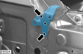
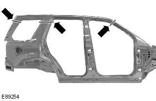
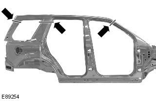
41. Cut off the old panel at the A-pillar and rear quarter panel using the new panel as a reference, making sure the new panel will overlap the panel remaining on the car.
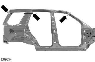
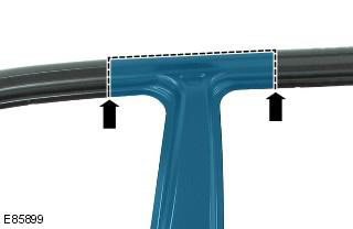
42. Cut off the old panel at the B-pillar as shown, taking into account the dimensions to gain access to the B-pillar reinforcement.
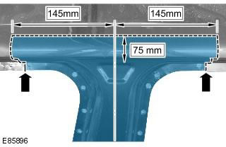
43. Mill out the weld spots.
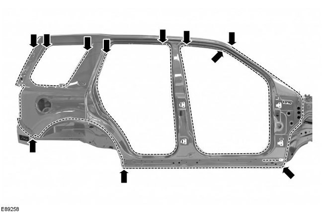
44. Separate the connections and remove the old panel, also disconnect the NVH elements.
Installation
1. Apply the new panel, align it and fix it in place, overlapping the old panel remaining on the car. Check the alignment, if correct, proceed to the next step, if not, correct and check again before proceeding to the next step.
2. Cut off the new and old panels at the A-pillar and rear quarter panel, making sure the new panel will overlap the panel remaining on the car.
3. Cut the new and old panels at the "B" post where the MIG butt joints are to be made.
4. Remove the new panel and the remains of the old one.
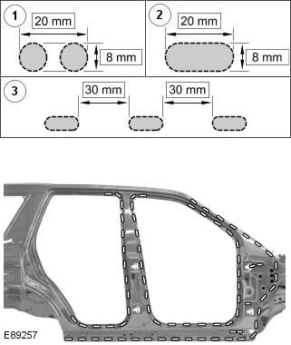
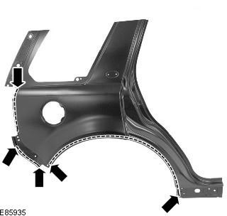
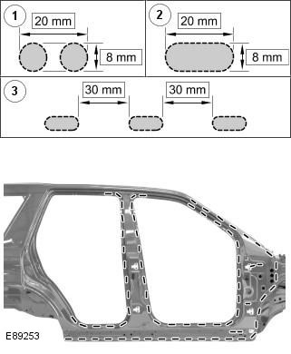
5. Cut holes in the new panel for MIG welding.
NOTE: Holes should be made for MIG brazing at the intervals shown in the illustration. Where this is not possible due to recesses in the panel, a hole should be made at the original weld spot.
6. Drill holes in the new panel for MIG welding.
7. Prepare the connecting surfaces of the old and new panels.
8. Replace NVH element/s if necessary.
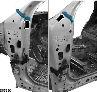
9. Apply sealing adhesive to the A-pillar NVH element.
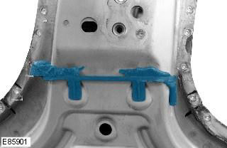
10. Apply sealing adhesive to the B-pillar NVH element.
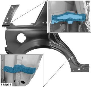
11. Apply sealing adhesive to the rear quarter panel NVH elements.
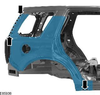
12. Apply glue to the "A" post as shown in the picture.
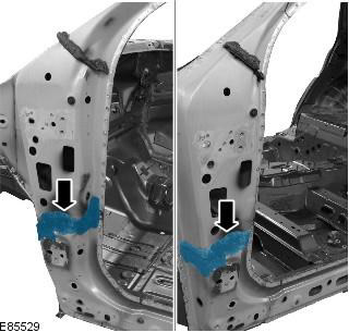
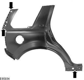
13. Apply glue to the rear side panel as shown in the picture.
14. Place the new panel and secure it in place.
15. Tack the butt joints.
16. MIG welding.
17. Spot welding.
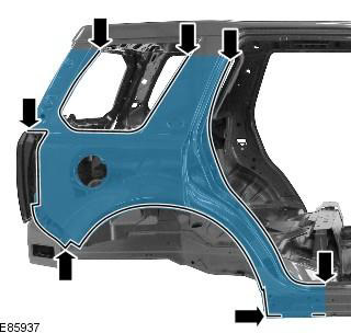
18. Perform MIG welding.
19. Clean the tack welds.
20. Perform MIG welding of the butt joint at the upper B-pillar.
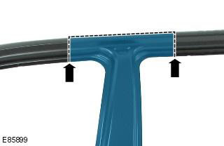
21. Perform MIG welding of butt joints at the A-pillar and rear side panel.
22. Clean all welded joints.
23. To install the relevant panels and mechanical components, perform the removal procedure in reverse order.
Comments on this article