Dismantling
1. Remove the cover covering the units in the engine compartment
2. Remove the main brake cylinder.
BRAKING SYSTEM, REPAIR WORKS, Brake master cylinder - tandem.
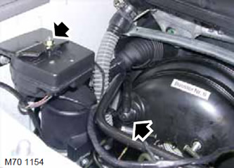
3. Disconnect the vacuum hose from the vacuum booster.
4. Remove the nut securing the siren to the bracket and move the siren to the side.
5. Remove the screw securing the pre-pressure pump bracket to the vehicle body.
6. Release the pump from the rubber support.
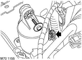
7. Disconnect the block with the electric cable.
8. Remove the pre-pressure pump.
9. Remove the protective shield.
CAR INTERIOR PARTS, REPAIR WORKS, Control panel lower cover.
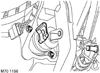
10. Take out cotter pin and remove the finger connecting a pusher of the vacuum booster with a brake pedal.
11. Turn away and throw out two nuts of fastening of the vacuum amplifier.
12. Remove the vacuum booster.
Assembly
1. Install a new vacuum booster gasket and reinstall the vacuum booster.
CAUTION: For right-hand drive models: When installing the vacuum booster, make sure that the air suspension hose is not pinched behind it.
2. Screw on new nuts of fastening of the vacuum amplifier and tighten them with the moment of 26 Нм.
CAUTION: The nuts connecting the vacuum booster to the pedal bracket must be re-tightened after 20 minutes.
3. Clean the pin and apply grease to it.
FILLING CAPACITIES, USED OPERATING LIQUIDS, OILS AND SEALANTS, Lubrication system.
4. Connect the pusher to the pedal, insert your finger and install the cotter pin in its hole.
5. Replace the protective shield.
CAR INTERIOR PARTS, REPAIR WORKS, Control panel lower cover.
6. Connect the pre-pressure pump to the rubber support.
7. Attach the cable block.
8. Install the screw securing the pre-pressure pump and tighten the screw with a torque of 8 Nm.
9. Install the siren on the bracket, screw on the fastening nut and tighten it with a torque of 8 Nm.
10. Connect the vacuum hose.
11. Establish the main brake cylinder.
BRAKING SYSTEM, REPAIR WORKS, Brake master cylinder - tandem.
12. Replace the cover that covers the units in the engine compartment.
Comments on this article