car logo Ford
car logo Volkswagen
car logo BMW
car logo Opel
car logo Audi
car logo Toyota
car logo Peugeot
English Русский
Български
Беларускі
Український
Српски
Hrvatski
Română
Polski
Slovenský
Magyar


Main
Freelander
Discovery
Range Rover
Defender
Contacts
Articles

Electronic control unit ABS (Range Rover 3)

 
  • Main
  • Range Rover
  • Range Rover 3
  • Chassis
  • Brake system
  • Electronic control unit ABS
 
        0  
Contents: Dismantling ⇩ Assembly ⇩
If the electronic control unit needs to be replaced, connect the Testbook/T4 diagnostic tool before disconnecting the battery to ensure the correct sequence of operations.

Before disconnecting the battery, make sure that all requirements and conditions contained in the section on disconnecting the battery are met.

GENERAL INFORMATION, Precautions when working with electrical equipment.

Dismantling


1. Disconnect the negative terminal from the battery.

2. Remove the 2 bolts securing the inlet pipe to the fuel cooler.

3. Remove the 2 bolts securing the fuel cooler inlet pipe to the hood lock panel.

4. Remove the fuel cooler inlet pipe.
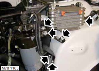
5. Unscrew the 2 nuts of the fuel filter mounting bracket, remove the filter with the bracket and…


5. Unscrew the 2 nuts of the fuel filter mounting bracket, remove the filter with the bracket and put it aside.

6. Remove the nut and 3 screws securing the fuel filter and cooler bracket and set the bracket assembly aside.
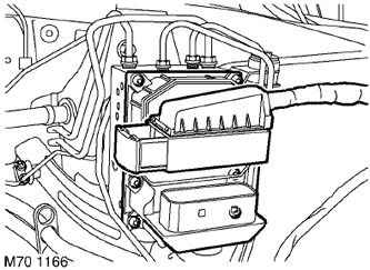
7. Release the retainer and disconnect the ABS pressure regulator connector block.


7. Release the retainer and disconnect the ABS pressure regulator connector block.


8. Remove the 6 Torx screws securing the ABS electronic control unit.

CAUTION: Before disconnecting or removing brake system components, make sure that the adjacent surfaces are free of dirt. Install plugs in the openings of the fittings and pipes to protect the system from dirt ingress.


9. Remove the ABS electronic control unit.

CAUTION: Do not touch the now exposed pressure regulator power relays as this may cause damage.

Assembly


1. Make sure the mating surfaces of the ABS electronic control unit and the pressure regulator are clean.

2. Install the ABS electronic control unit onto the pressure regulator, install the Torx screws and tighten them to 2.9 Nm.

3. Connect the connector to the pressure regulator connector.

4. Install the fuel filter and fuel cooler bracket, screw on the mounting nut, tighten the screws and tighten them to 8 N·m.

5. Install the fuel filter with the retaining clip and tighten the nuts to 25 N·m.

6. Install the inlet pipe assembly and tighten the screws securing the pipe to the fuel cooler.

7. Align the end of the fuel cooler inlet pipe with the hood lock panel, install the mounting screws and tighten them to 3 N·m.

8. Connect the negative terminal to the battery.

The source of the article is located on the website: LRMAN.ru


This article is available at russian, bulgarian, belarusian, ukrainian, serbian, croatian, romanian, polish, slovak, hungarian
Article review: Platon Fedorov


Previous articles
Checking the wear and runout of the front brake disc
Checking the wear and runout of the rear brake disc
Bleeding the brake system
Adjusting the parking brake
Front brake disc
Rear brake disc
Pre-pressure pump
Brake system reservoir

Current article
Electronic control unit ABS

Next articles
ABS Front Wheel Speed Sensor
Rear wheel speed sensor
ABS pressure regulator unit
ABS Pressure Regulator Pressure Sensor
Dynamic stability control system sensor


Similar articles from Land Rover repair manuals:
• Electronic glow plug control unit: up to May 2003 Freelander 1 (1997-2006)
• Rotary controller and system control unit Freelander 2 (2006-2014)
• Electronic control unit for rear differential Discovery 3 (2004-2009)
• Electronic control unit coding plug Discovery 1 (1989-1998)
• Hydraulic Control Unit (HCU) Defender 2007+ (2007-2016)

Comments on this article


No comments yet


How much will 23 + 16 =


Range Rover 3 
  • General information
  • Using the manual
  • Precautionary measures
  • Repair techniques
  • Identification codes
  • Specifications
  • Tightening torques
  • Materials
  • Maintenance
  • Power unit
  • Diesel engine TD6
  • Petrol engine V8
  • Emission reduction TD6
  • Emission reduction V8
  • Engine management TD6
  • Engine management V8
  • Fuel supply TD6 engine
  • Fuel supply V8 engine
  • Engine cooling TD6
  • Engine cooling V8
  • Exhaust system TD6
  • Exhaust system V8
  • Transfer case
  • Automatic gearbox GM-5L40-E
  • Automatic gearbox ZF 5HP24
  • Chassis
  • Drive shafts
  • Main gear
  • Front axle gear
  • Steering
  • Front suspension
  • Rear suspension
  • Brake system
  • Body and coating
  • Passenger safety
  • Doors and windows
  • Exterior details
  • Interior details
  • Glasses
  • Seats
  • Sunroof
  • Body geometry
  • Body repair
  • Corrosion protection
  • Electrical equipment
  • Heating and ventilation
  • Conditioning
  • Windshield wipers and washers
  • Starting and charging system
  • Lighting and headlights
  • Electronic blocks
  • Entertainment system
  • Wiring harnesses


LRman.ru © 2013-2026 | Mobile version | Free Lander | Discovery | Range Rover | Defender | Contacts | | Sitemap |
Car repair and service instructions Land Rover: Freelander, Discovery, Range Rover, Defender
We use cookies to make pages load faster and provide a more user-friendly experience 🍪