Dismantling
1. Remove the valve cover of the left cylinder head.
V8 engine, ENGINE OVERHAUL, Valve cover gasket.
2. Remove 8 spark plugs.
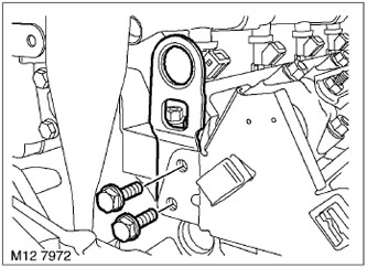
3. Turn away 2 bolts of fastening of a back lifting eye on the right head of cylinders and remove an eye.
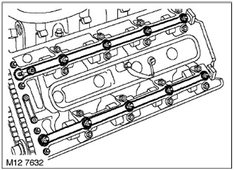
4. Turn away 20 nuts of fastening of 4 oil-distributing tubes of greasing of cam-shafts of the left and right heads of cylinders and remove oil-distributing tubes.
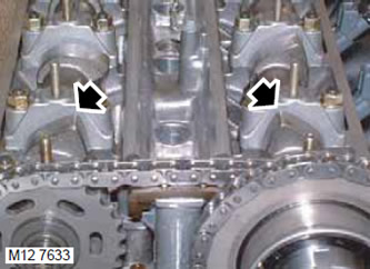
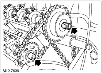
5. Turn the crankshaft so that the camshaft cams on the first cylinder are in the T.M.T position of the start of the working cycle.
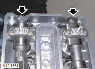
6. The rear of the camshaft may appear to be misaligned and misaligned with cylinder #1 cams at T.M.T. start of the working cycle.
NOTE: The seemingly incorrect position of the camshafts does not indicate incorrect valve timing.
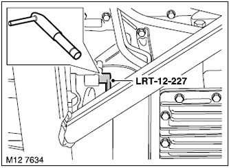
7. Insert pin LRT-12-227 through hatch and lock flywheel in T.D.T.
8. Remove the upper front covers of the timing mechanism drive.
V8 Engine, ENGINE OVERHAUL, Top Timing Cover. Disassembly
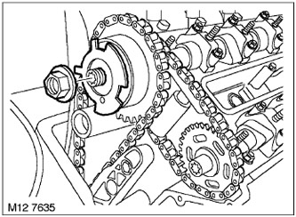
1. Remove the left camshaft position sensor disk nut and remove the disk.
NOTE: This thread is left handed.
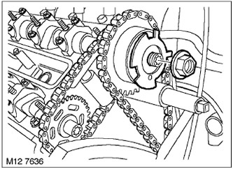
2. Turn away a nut of fastening of a disk of the sensor of position of a cam-shaft of the right head and remove a disk.
NOTE: This thread is left handed.
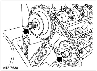
3. Loosen the 2 left head VCC bolts and the left head exhaust camshaft sprocket by half a turn.
NOTE: This thread is left handed.
4. Loosen the 2 bolts securing the right head VCC and the right head exhaust camshaft sprocket by half a turn.
NOTE: This thread is left handed.
5. Loosen the bolt securing the mandrel LRT-12-223/2 to the mandrel LRT-12-223/1.
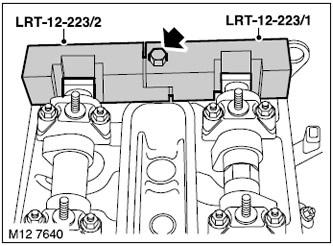
6. Install mandrels LRT-12-223/2 and LRT-12-223/1 on the rear of the right cylinder head camshafts and tighten the bolt.
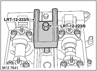
7. Install mandrels LRT-12-223/5 and LRT-12-223/6 on the right cylinder head and tighten mandrel LRT-12-223/6 using the threaded socket of the spark plug.
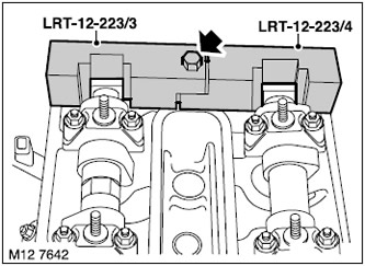
8. Loosen the bolt securing the mandrel LRT-12-223/4 to the mandrel LRT-12-223/3.
9. Install mandrels LRT-12-223/4 and LRT-12-223/3 on the rear of the camshafts of the left cylinder head and tighten the bolt.
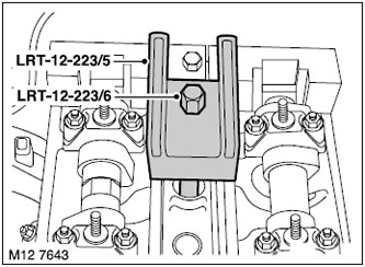
10. Install mandrels LRT-12-223/5 and LRT-12-223/6 on the left cylinder head and tighten LRT-12-223/6 using the threaded socket of the spark plug.
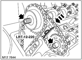
11. Compress the left head exhaust chain tensioner spring, insert the LRT-12-220 pin into the tensioner and remove the 2 bolts securing the VCC and the exhaust camshaft sprockets.
NOTE: This thread is left handed.
12. Remove the exhaust camshaft sprocket, exhaust drive chain and left head VCC.
NOTE: To prevent the chain from falling down, attach it to the cylinder head.
Assembly
1. With the drive chain on the left head VCC, install the VCC and exhaust camshaft sprocket onto their camshafts, screw in and tighten the 2 mounting bolts to eliminate play.
NOTE: This thread is left handed.
2. Compress the left head exhaust camshaft chain tensioner spring and remove pin LRT-12-220.
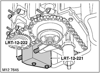
3. Install Drift LRT-12-221 on Right Cylinder Head, fasten Drift LRT-12-222 to LRT-12-221 and tighten by hand.
NOTE: Turn the adjusting bolt in only until there is slight resistance.
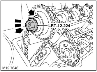
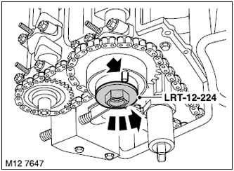
4. Install tool LRT-12-224 on the VCC of the left cylinder head and connect a tester between the contact on the RFG and the stud on the oil distribution tube.
5. Rotate the VCC of the left head counter-clockwise using the tool LRT-12-224 until the rotational force reaches 40 Nm, using a tester, check the continuity of the circuit.
NOTE: Turning the VCC on the LRT-12-224 removes excess oil and brings the VCC to its stop. The circuit is closed when VCC reaches the stop.
6. Tighten the left VCC and exhaust camshaft sprocket bolts to 15 Nm and loosen a quarter of a turn.
NOTE: This thread is left handed.
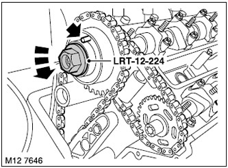
7. Install tool LRT-12-224 on the VCC block of the right cylinder head and connect a tester between the pin on the VCC and the stud on the oil distribution tube.
8. Rotate the right head VCC block counterclockwise using the LRT-12-224 tool until the rotation force reaches 40 Nm, using a tester, check the continuity of the circuit.
NOTE: Turning the VCC on the LRT-12-224 removes excess oil and brings the VCC to its stop. The circuit is closed when VCC reaches the stop.
9. Tighten the bolts securing the right VCC block and exhaust camshaft sprocket to 15 Nm and loosen a quarter of a turn.
NOTE: This thread is left handed.
10. Adjust chain tension by tightening tool LRT-12-222 to 0.7 Nm.
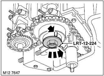
11. Install tool LRT-12-224 on the left cylinder head VCC block and connect a tester between the pin on the VCC and the stud on the oil distribution tube.
NOTE: When adjusting the chain tension, the VCC is shifted, after which it is required to bring it to the left stop.
12. Rotate the VCC of the left head counterclockwise using the tool LRT-12-224 until the rotational force reaches 40 Nm, using a tester, check the continuity of the circuit.
NOTE: Turning the VCC on the LRT-12-224 removes excess oil and brings the VCC to its stop. The circuit is closed when VCC reaches the stop.
13. Tighten the left VCC bolts to 110 Nm, and the exhaust sprocket bolt to 125 Nm.
NOTE: This thread is left handed.
14. Install tool LRT-12-224 on the right cylinder head VCC block and connect a tester between the pin on the VCC and the stud on the oil distribution tube. NOTE: When adjusting the chain tension, the VCC is shifted, after which it is required to bring it to the left stop.
15. Rotate the right head VCC block counterclockwise using the LRT-12-224 tool until the rotation force reaches 40 Nm, using a tester, check the continuity of the circuit.
NOTE: Turning the VCC on the LRT-12-224 removes excess oil and brings the VCC to its stop. The circuit is closed when VCC reaches the stop.
16. Tighten the right VCC bolts to 110 Nm, and the exhaust sprocket bolt to 125 Nm.
NOTE: This thread is left handed.
17. Install the camshaft position sensor disc on the right cylinder head and tighten the disc mounting nut by hand.
NOTE: This thread is left handed.
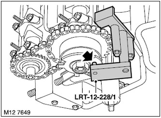
18. Install the latch LRT-12-228 / 1 on the sensor disc of the right camshaft position head, screw in 2 bolts securing the latch to the right cylinder head and tighten them.
NOTE: In order to properly adjust the position of the camshaft position sensor disc, before tightening the retainer mounting bolts, make sure that the tool is firmly seated on the surface of the cylinder head and on the bottom of the engine front cover (timing cover).
19. Tighten the camshaft position sensor disc mounting nut to 40 Nm and remove the LRT-12-228/1 retainer from the right cylinder head.
NOTE: This thread is left handed.
20. Establish the left disk of the gauge of position of a camshaft and tighten by force of a hand a nut of fastening of a disk.
NOTE: This thread is left handed.
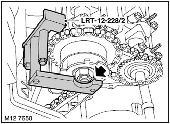
21. Install the LRT-12-228 / 2 retainer on the left camshaft position sensor disk, screw in the 2 bolts securing the retainer to the left cylinder head and tighten them.
NOTE: In order to properly adjust the position of the camshaft position sensor disc, before tightening the retainer mounting bolts, make sure that the tool is firmly seated on the surface of the cylinder head and on the bottom of the engine front cover (timing cover).
22. Tighten the nut securing the camshaft position sensor disc to a torque of 40 Nm and remove the LRT-12-228 / 2 retainer from the left cylinder head.
NOTE: This thread is left handed.
23. Remove the LRT-12-223/6, LRT-12-223/5, LRT-12-223/2 and LRT-12-223/1 tools from the right cylinder head camshafts.
24. Remove the LRT-12-223/6, LRT-12-223/5, LRT-12-223/3 and LRT-12-223/4 tools from the left cylinder head camshafts.
25. Loosen LRT-12-222, remove 2 bolts securing LRT-12-222 to right cylinder head and remove tool LRT-12-221.
Assembly
1. Install the upper front timing cover.
V8 Engine, ENGINE OVERHAUL, Top Timing Cover.
2. Remove the LRT-12-227 pin from the retainer hole.
3. Install 4 oil distribution tubes on the left and right cylinder heads, screw in and tighten the 20 mounting bolts.
4. Establish a back lifting eye of the right head of cylinders, screw and tighten 2 bolts of its fastening.
5. Screw in and tighten 8 spark plugs. Tightening torque 23 Nm.
6. Install valve cover gaskets.
V8 engine, ENGINE OVERHAUL, Valve cover gasket.
Comments on this article