Dismantling
1. Remove the upper front timing chain covers.
V8 Engine, ENGINE OVERHAUL, Upper Timing Belt Cover.
2. Remove the front crankshaft oil seal.
V8 Engine, ENGINE OVERHAUL, Front Crankshaft Oil Seal.
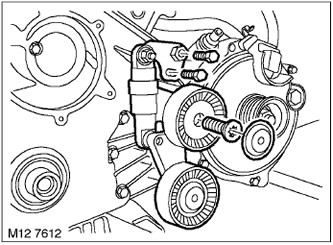
3. Unscrew the 2 bolts securing the accessory drive belt tensioner to the lower timing mechanism cover.
4. Remove the dust cover from the belt roller and unscrew the Torx bolt securing the belt roller.
5. Remove the accessory drive belt tensioner.
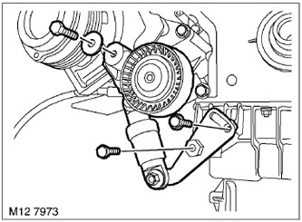
6. Unscrew the 2 bolts securing the air conditioning system compressor drive belt tensioner.
7. Remove the remaining bolt securing the air conditioning compressor drive belt tensioner.
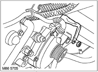
8. Loosen the nut and disconnect the battery cable from the generator.
9. Disconnect the battery cable from the lower timing belt cover.
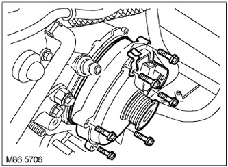
10. Unscrew the 6 generator mounting bolts and the generator harness clamp.
11. Remove the generator from the lower timing cover.
12. Discard the generator sealing ring.
(The original text was published on the website: LRMAN.RU)
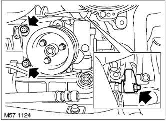
13. Unscrew 2 bolts and 1 nut securing the power steering pump and move the pump to the side.
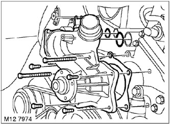
14. Unscrew the 6 bolts of the cooling system pump.
15. While supporting the coolant hoses, remove the coolant pump and discard the pump O-rings.
Disassembly

1. Remove the 6 bolts securing the lower timing belt cover to the upper part of the oil pan.
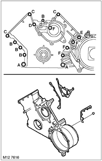
2. Unscrew the 15 bolts securing the lower timing belt cover to the cylinder block.
NOTE: Mark the position of all bolts as they are different lengths.
- A = M8 x 75 mm
- B = M6 x 40 mm
- C = M6 x 85 mm
- D = M6 x 80 mm
- E = M8 x 90 mm
- F = M6 x 60 mm
3. Remove the lower front timing cover.
4. Discard the 3 lower timing cover gaskets.
Examination
1. Wipe the timing cover and mating surface, pins and pin seats.
Assembly
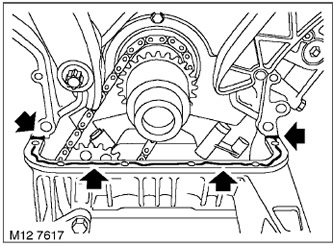
1. Apply STC 50550 sealant to the areas shown in the figure.
2. Install 3 new lower timing cover gaskets.
3. Install the lower front timing cover.
4. Screw in 15 bolts securing the lower timing cover to the cylinder block and pre-tighten them to a torque of 5 N·m.
5. Tighten the M6 bolts securing the bottom cover to a torque of 10 N·m, and the M8 bolts to a torque of 22 N·m.
CAUTION: After tightening all bolts, check their tightening torque.
6. Install the 6 bolts securing the lower timing belt cover to the upper oil pan and tighten to 12 Nm.
Assembly
1. Lubricate new O-rings and install them into the grooves on the pump body.
2. Wipe the cooling system pump and mating surfaces.
3. Install a new gasket on the coolant pump, install the pump on the engine, screw in the bolts and tighten them to a torque of 10 N·m.
4. Install the power steering pump in place and tighten the mounting screws and mounting nut. Tighten the pump mounting screws to 10 N·m and the mounting nut to 25 N·m.
5. Clean the mating surfaces of the generator and the timing gear cover.
6. Lubricate the new O-ring and install it on the generator.
7. Install the generator and tighten the mounting bolts.
8. Secure the battery cable to the lower timing belt cover.
9. Connect the battery cable to the generator and tighten the nut to 13 N·m.
10. Install the air conditioning compressor drive belt tensioner in place and secure it with the bolt, but do not tighten it yet.
11. Install the 2 A/C compressor drive belt tensioner bolts to the top of the oil pan, but do not tighten them yet.
12. Install the accessory drive belt tensioner, screw in the idler pulley mounting bolt and tighten it.
13. Place the dust cap on the tensioner idler pulley.
14. Install the 2 bolts securing the accessory belt tensioner to the lower timing belt cover, but do not tighten them yet.
15. Install the front crankshaft oil seal.
V8 Engine, ENGINE OVERHAUL, Front Crankshaft Oil Seal.
16. Install the upper front timing chain covers.
V8 Engine, ENGINE OVERHAUL, Upper Timing Belt Cover.
Comments on this article