Contents: Electronic throttle ⇩ Electronic Throttle Valve Connector…⇩ Accelerator pedal position sensor ⇩ Pinout table of connector C0787…⇩
The 4.0-liter gasoline engine's acceleration is controlled by an electronic throttle valve, which is linked to a drive-by-wire control unit. The throttle valve is electronically linked to the ECM, which regulates fuel delivery in accordance with requests from the accelerator pedal position (APP) sensor.
Electronic throttle
Electronic throttle body
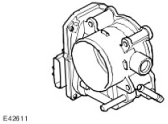
An electronic throttle regulates the air flow to the engine. In addition to the usual functions of regulating engine power, an electronic throttle performs functions such as cruise control, idle control, and maximum engine speed limitation, without the need for additional hardware.
The electronic throttle assembly consists of a throttle body in which the throttle valve is mounted, driven by a DC motor via a gearbox. A return spring moves the throttle valve toward the closed position.
The ECM controls the operation of the DC motor by sending two pulse width modulation (PWM) signals to the H-bridge exciter circuit in the motor. The eCm varies the speed and direction of the motor by changing the duty cycle of the PWM signals.
To provide closed-loop control, the ECM determines throttle position using two Hall Effect sensors in the throttle body. These sensors share a common 5-volt supply and ground connection with the ECM and generate separate linear voltage signals proportional to throttle position that are sent to the ECM. The ECM uses the signal from sensor 1 as the primary throttle position signal and uses the signal from sensor 2 to verify the validity of the primary signal.
- The signal voltage of sensor 1 can vary from 0.5 V (throttle valve fully closed) up to 4.5 V (throttle fully open).
- The signal voltage of sensor 2 can vary from 4.5 V (throttle valve fully closed) up to 0.5 V (throttle fully open).
- Writes the corresponding fault code into memory.
- Turns on the SERVICE ENGINE indicator lamp on the instrument panel.
- Depending on the nature of the malfunction, it switches to emergency throttle control mode or stops controlling the throttle.
- If one throttle position sensor or controller in the ECM is faulty, the ECM limits the vehicle's acceleration by limiting the throttle angle.
- If both sensors are faulty, the ECM stops fuel delivery, limiting engine speed to 1300 rpm.
Electronic Throttle Valve Connector C0175 Contacts
| Contact No. | Description | Input signal/output signal |
| 1 | APP sensor 1 | Input signal |
| 2 | Reference voltage 5V | Input signal |
| 3 | APP 2 sensor | Input signal |
| 4 | Sensor mass | - |
| 5 | Throttle valve (+) | Input signal |
| 6 | Throttle valve (-) | Input signal |
Accelerator pedal position sensor
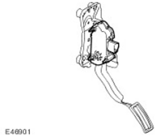
The accelerator pedal position (APP) sensor is an integral part of the accelerator pedal assembly.
The APP sensor allows the ECM to determine the throttle position requested by the driver via the accelerator pedal.
The APP sensor is located in the pedal box and consists of a two-track potentiometer, the sliders of which are connected to the accelerator pedal by means of rods. Each track of the potentiometer is supplied with 5 V power and a ground connection from the ECM. The potentiometer generates a linear voltage signal proportional to the position of the accelerator pedal and transmits it to the ECM. The signal voltage from track 1 of the potentiometer is approximately twice as high as the signal voltage from track 2.
From the sensor signals, the ECM determines the driver's request as a percentage of pedal travel, where 0% corresponds to the pedal being released and 100% corresponds to the pedal being fully depressed. The driver's request is then used to calculate the throttle angle, fuel quantity, and ignition timing. In addition, the ECM transmits the driver's request via the CAN system for use by the transmission and brake control systems.
The ECM stores the signal values corresponding to the fully closed and fully open positions and adopts new values to compensate for replacement or wear of parts or assemblies.
The ECM constantly monitors the APP sensor signals for shorts, opens, and plausibility. If a fault is detected, the ECM:
- Writes the corresponding fault code into memory.
- Turns on the SERVICE ENGINE indicator lamp on the instrument panel.
- Disables the transmission of driver requests via the CAN bus, which results in the disabling of the ABS modulator's automatic hill descent control function and reduces the performance of the automatic transmission (gears shift more sharply and the downshift function is disabled).
- Switches to emergency throttle control mode.
- If a fault is detected in only one potentiometer track, the ECM limits vehicle acceleration by limiting the throttle valve opening angle.
- If a fault is detected in both tracks of the potentiometer, the ECM, using the throttle valve, maintains the engine speed at 1472 rpm with the brake pedal released and at 750 rpm (idling) - when the brake pedal is pressed or when the brake light switch fails.
- If a fault is detected in the ECM, the ECM stops fuel delivery, limiting engine speed to 1300 RPM, or stops fuel injection to stop the engine.
Pinout table of connector C0787 accelerator pedal position sensor
| Contact No. | Description | Input signal/output signal |
| 1 | Mass of the APP sensor 1 | - |
| 2 | APP Request 1 | Output signal |
| 3 | APP Request 2 | Output signal |
| 4 | Normally closed | - |
| 5 | Mass of the APP sensor 2 | - |
| 6 | Reference voltage 2 | Input signal |
| 7 | Reference voltage 1 | Input signal |
Comments on this article