Dismantling
1. Remove the oil pump.
V8 engine, ENGINE OVERHAUL, Oil pump.
Disassembly
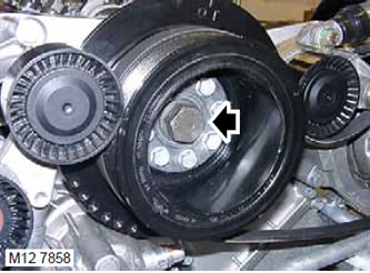
1. Using a socket on the pulley bolt and a wrench, turn the crankshaft in the direction of normal rotation to gain access to the connecting rod bolts.
2. Mark connecting rods and connecting rod caps by cylinder number.
NOTE: The connecting rod caps and connecting rods have marks that align when assembled.
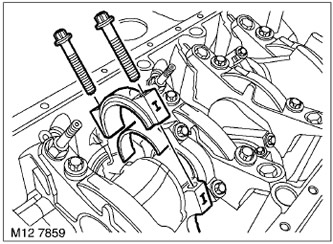
3. Loosen and remove the connecting rod bolts, save them for now.
4. Remove connecting rod caps, remove and dispose of connecting rod bearings.
5. Move the connecting rod away from the crankpin.
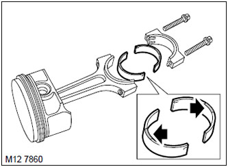
6. Remove the bushing from the connecting rod and discard it.
NOTE: Connecting rod bearings with a blue mark are installed in the connecting rod, and those with a red mark are installed in the lower head cover.
7. Do the same with the rest of the connecting rod bearings. Lay out the connecting rod caps in the order they were on the engine.
Examination
1. Wipe the crankpins, new liners, beds of the upper and lower liners.
2. Measure the diameters of all connecting rod journals, making 4 measurements at 90°intervals on each journal. Write down the measurement results.
TECHNICAL DATA, Engine - V8.
3. Wipe and lubricate the old connecting rod bolts.
4. Turn the crankshaft with the connecting rod journal to the N.M.T.
5. Insert a new blue-marked bearing into the connecting rod.
6. Insert a new insert with a red marking into the connecting rod cover.
7. Put the connecting rod on the crankpin.
8. Place a strip of deformable calibration material on the crankpin ("plastigage").
9. Put on the connecting rod cover, making sure that the alignment marks on the connecting rod and on the connecting rod cover are aligned.
CAUTION: Do not turn the crankshaft while using the calibration material.
10. Screw in the old connecting rod bolts and pre-tighten them to 5 Nm, then tighten them to 20 Nm and then tighten them 80°.
CAUTION: Do not turn the crankshaft while using the calibration material.
11. Turn away bolts of fastening of a rod cover and remove it.
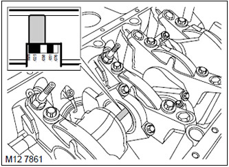
12. Using a special ruler, measure the width of the calibration strip and use this value to determine the amount of clearance in the connecting rod bearings.
13. If with this set of liners it is not possible to achieve the desired clearance value, then the crankshaft journals must be ground to the next repair size and liners of the corresponding repair size should be installed.
TECHNICAL DATA, Engine - V8.
14. Leave the approved liners in the connecting rod and in the connecting rod cap.
15. Using clean engine oil and a cloth, remove any remnants of the calibration strip.
16. Do the operations described above on the remaining connecting rod journals.
17. After checking the clearances in the connecting rod bearings is completed, dispose of the used connecting rod bolts.
Assembly
1. Lubricate the connecting rod journals and approved connecting rod bearings with clean engine oil.
2. Put the connecting rod on the crankpin, making sure the bushing is in the correct position.
3. Put on the connecting rod cover, making sure that the alignment marks on the connecting rod and on the connecting rod cover are aligned.
4. Wipe and lubricate the new connecting rod bolts.
5. Screw in new connecting rod bolts and pre-tighten them to 5 Nm, then tighten them to 20 Nm and then tighten them by 80°.
Assembly
1. Install the oil pump.
V8 engine, ENGINE OVERHAUL, Oil pump.
Comments on this article