Disassembly

1. Unscrew the 2 exhaust camshaft drive chain tensioner mounting nuts, remove the tensioner and discard the O-ring.
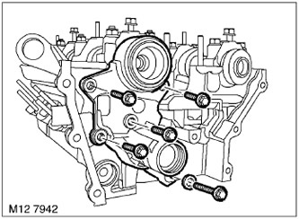
2. Unscrew the 5 bolts securing the valve timing adjuster housing. Remove the sealing washer from the long bolt and dispose of it.
3. Remove the oil distributor housing, remove and discard the gasket.
NOTE: If the oil distributor is worn, loosen it from the sealing rings by moving it back and forth.

4. Carefully separate and remove the 3 RFG oil distributor sealing rings from the intake camshaft.
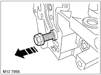
5. Screw the M10 bolt into the RFG check valve and, pulling by hand, remove the valve from the cylinder head. Dispose of the sealing ring.
[The full version is available on the website LRman.ru]
6. Check the axial play of the camshaft using a dial indicator.
TECHNICAL SPECIFICATIONS, Engine - V8.
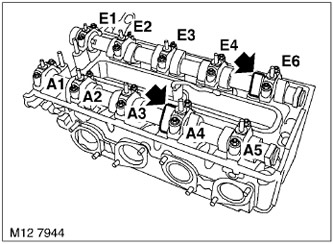
7. Using a hex wrench, turn the intake camshaft until the tops of the cams on cylinder 8 point upward.
8. Using a hex wrench, turn the exhaust camshaft until the tops of the cams of the 6th cylinder are facing upward.
9. Note how the camshaft bearing caps are marked. The intake camshaft is marked "E" and its caps are labeled "E1" through "E5" from the front (driven) end of the camshaft, viewed from the intake side. The exhaust camshaft is marked "A" and its caps are labeled "A1" through "A5" from the front (driven) end of the camshaft, viewed from the intake side.
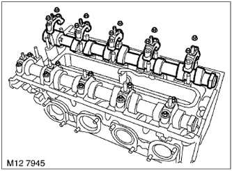
10. Evenly and sequentially loosen and unscrew the 10 intake camshaft cover mounting nuts.
11. Remove the camshaft covers.
12. Remove the intake camshaft.
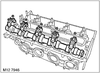
13. Evenly and sequentially loosen and unscrew the 10 exhaust camshaft cover fastening nuts.
14. Remove the camshaft covers.
15. Remove the exhaust camshaft.
16. Remove the hydraulic compensators. If you intend to use them further, arrange them in the order in which they were installed.
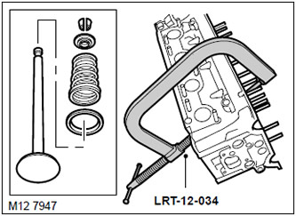
17. Install the LRT-12-034 valve spring compressor onto the valve plate and compress the valve spring.
18. Remove 2 crackers and remove the valve spring compressor.

19. Remove the valve stem seals using the LRT-12-071 pliers. Discard the seals.
20. Do the same on the remaining valves, laying out the removed parts in the order in which they were on the cylinder head.
Examination
1. Check the condition of the camshafts. If they are scratched, dented or excessively worn, replace the camshafts.
TECHNICAL SPECIFICATIONS, Engine - V8.
2. Check the degree of wear of the camshaft journals and beds.
TECHNICAL SPECIFICATIONS, Engine - V8.
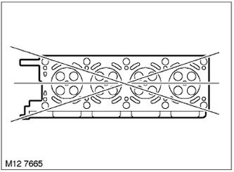
3. Using a straightedge and feeler gauge, check the deformation of the lower plane of the head in the directions shown in the figure.
TECHNICAL SPECIFICATIONS, Engine - V8.
4. Check the condition of the valve seats for dents, burnouts, cracks and wear.
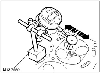
5. Insert the new valve into the guide so that the top of the valve stem is on the cut of the guide sleeve.
6. Install a dial indicator on the cylinder head and set the indicator to "zero" by resting its leg on the valve plate. By rocking the valve from side to side, determine the degree of wear of the valve guide.
TECHNICAL SPECIFICATIONS, Engine - V8.
7. If the valve movement in the sleeve is too great, then the sleeve hole must be expanded to accommodate valves with a larger stem diameter.
TECHNICAL SPECIFICATIONS, Engine - V8.
8. After the bushings have been expanded to accommodate valves with a larger stem diameter, the seats must be adjusted using special tools LRT-12-501, LRT-12-503 and LRT-12-517.
TECHNICAL SPECIFICATIONS, Engine - V8.
9. Make sure that the cutters are in the correct position in the cutting head. The cutters should cut the chamfer of the seat with their middle part. Do not apply significant force when cutting and remove a minimum amount of material from the seat.
10. If necessary, repeat these operations on the remaining valves, guides and valve seats.
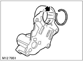
11. Check the wear of the VCC oil distributor housing and sealing rings.
TECHNICAL SPECIFICATIONS, Engine - V8.
CAUTION: Replace the housing and rings if there are obvious dents or scoring in the longitudinal direction.
Assembly
1. Remove carbon deposits from the guide bushings and inlet channels, blow with compressed air.
2. Wipe the valves, valve springs, upper and lower spring retainers and crackers.
3. Lubricate the valve with clean engine oil and insert it into the guide.
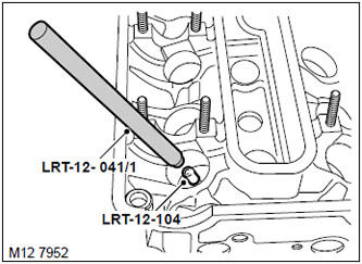
4. Put the protective cover LRT-12-104 on the stem, put the oil scraper cap on the valve and remove the cover LRT-12-104. Press the cap onto the guide sleeve using the mandrel LRT-12-041/1.
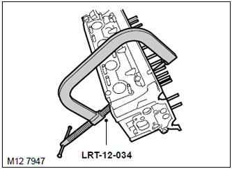
5. Insert the lower plates into the head, put the valve springs on the upper plates.
6. Use the LRT-12-034 valve spring compressor to compress the valve spring. Put on the valve spring crackers and carefully release the spring.
7. Do the same with the remaining valves.
8. Wipe the tappets, tappet beds, make sure the oil channels are clean.
9. Lubricate the tappets and their beds and insert the tappets into their original places.
10. Wipe the camshafts.
11. Wipe the camshaft beds. Make sure the oil passages are clean.
12. Lubricate the camshaft, its bearings and covers.
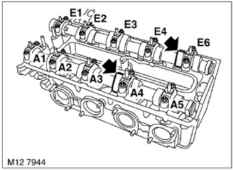
13. Install the exhaust camshaft with the cam apexes of the 6th cylinder facing up. Install the caps with the letter "A" in the correct order, tighten the nuts evenly and consistently to a torque of 14 N·m.
14. Install the intake camshaft with the cam apexes of the 8th cylinder facing up. Install the covers marked "E" in the correct order, tighten the nuts evenly and consistently to a torque of 14 N·m.
15. Wipe the VCC oil check valve, make sure the oil passages are clean.
16. Install the VCC oil check valve into the cylinder head using a new O-ring.
CAUTION: The VCC check valve must be installed so that the M10 thread remains visible.
17. Wipe the VCC oil rings and intake camshaft journal grooves.
18. Lubricate the oil distribution rings and carefully install them into the grooves of the intake camshaft.
19. Wipe the mating surfaces of the VCC oil distributor housing and cylinder head. Make sure the oil passages are clean.
20. Install the VCC oil distributor housing gasket onto the cylinder head.
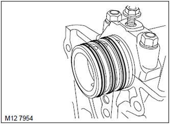
21. Install all VCC rings with the gaps facing up, place the housing on them and install it on the cylinder head.
22. Place a new sealing washer on the long bolt and tighten the VCC housing mounting bolts to 10 N·m.
23. Wipe the exhaust camshaft chain tensioner and mating surface. Make sure the oil feed channel is clean.
24. Lubricate the exhaust camshaft chain tensioner.
25. Install the exhaust camshaft chain tensioner with a new O-ring and tighten the bolts to 10 N·m.
26. Wipe the exhaust manifold and the mating surface on the cylinder head.
27. Install the exhaust manifold onto the cylinder head using new gaskets.
28. Screw on the exhaust manifold mounting nuts and tighten them. Tightening torque 24 Nm.
Comments on this article