Removing
All cars
NOTE: This procedure requires the body to be removed from the body subframe. This procedure can only be performed on a 2 post lift.
1. Open the tailgate.
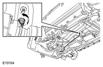
2. Disconnect a wire of weight from the accumulator. For more information refer to Specification.
3.
WARNING: Do not work on or under a vehicle that is only supported by a jack. Always place secure supports under the vehicle.
Raise the car with a jack and install supports.
Vehicles with manual transmission.
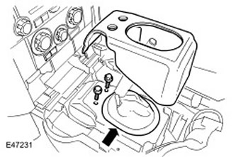
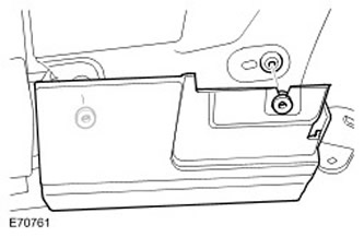
4. Remove the floor console top panel. For more information, refer to Floor Console Top Panel (76.25.11)
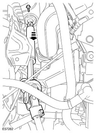
5. Disconnect the shift lever support bracket.
- Remove the sound deadening pad.
- Release the protective cover.
- Turn out two bolts.
All cars
6. Remove wheels with tires.
7. Drain the coolant from the cooling system. For more information, refer to Draining/Filling Coolant and Bleeding the Cooling System (26.10.01)
8. Drain the refrigerant from the air conditioning system (A/C). For more information, refer to Refrigerant Recovery, Vacuuming and Charging the Air Conditioning System (A/C) (82.30.02)
9. Remove the air filter assembly. For more information refer to Air Filter (19.10.01)
Vehicles manufactured since 01/2007
10. Disconnect the engine coolant temperature sensor connector (ECT).
- Release the clamp.
All cars
11. Remove the AWD control module (4WD). For more information refer to Four Wheel Drive Control Module (4WD) (41.30.01)
12. Disconnect the positive cable from the battery.
- Remove the BJB cover.
- Loosen the nut.
- Loosen the sealing sleeve.
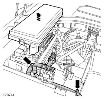
13. Remove the side wall of the battery compartment.
- Release the positive battery cable and grommet.
- Release 4 clips.
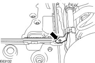
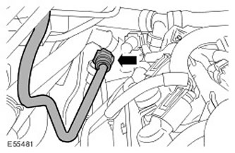
14. Release the heater pipes.
- Remove the screw.
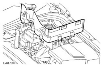
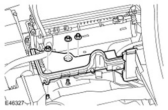
15. Remove the battery tray..
- Remove three nuts.
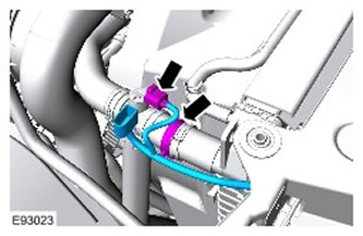
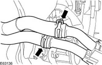
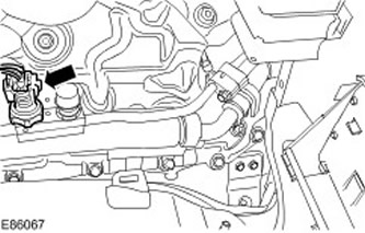
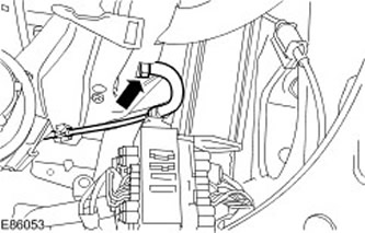
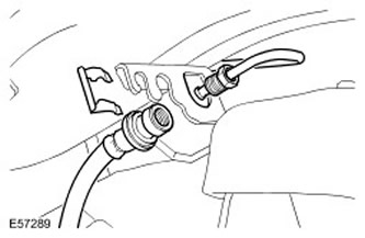
16. Disconnect the heater supply and return hoses.
- Release 2 clamps and disconnect hoses.
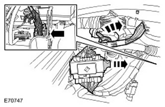
17. Remove the extra battery tray. For more information, refer to Additional Battery Shelf (76.10.31)
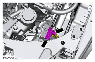
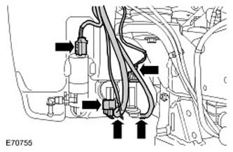
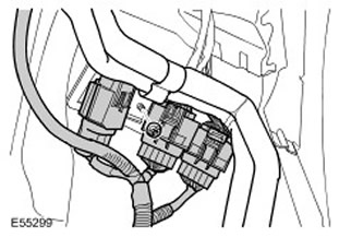
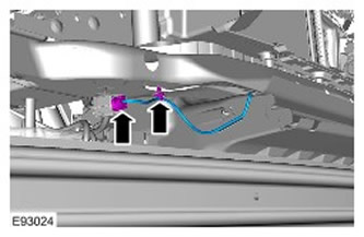
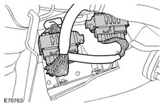
18. Release and disconnect 2 electric sockets of a plait of electroconducting of the engine.
19. Release and disconnect 2 electric sockets of a plait of electroconducting of a transmission.
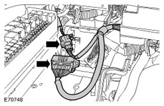
20. Release the wiring harness cassettes on the engine and transmission and position them to the side.
- Release two clamps.
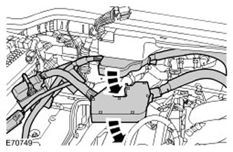
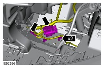
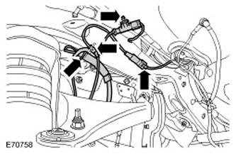
21. Disconnect the electrical connectors for the glow plugs.
- Release the glow plug wiring harness.
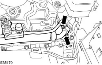
22.
CAUTION: Plug all openings. Install new plugs.
Disconnect the high and low pressure air conditioning lines.
- Turn out two bolts.
- Remove and discard 2 o-rings.
23. Disconnect the A/C low pressure sensor electrical connector.
- Release the wiring harness from the mount.
24.
CAUTION: Plug all openings. Install new plugs.
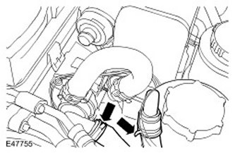
- Disconnect the brake booster vacuum hose.
25.
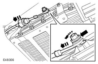
CAUTION: Do not turn the steering wheel with the lower steering column shaft disconnected as damage to the coil spring and switches located on the steering wheel may occur.
CAUTION: Make sure the wheels are in a straight-line position.
NOTE: Mark the installation position.
Remove the lower shaft of a steering column.
- Loosen and discard the upper steering column lower shaft bolt.
26. Remove the mudguards of both front fenders. For more information refer to Fender Mudguard (76.10.48)
27. Remove both lower wing moldings.
- Release two clamps.
- Repeat the above procedure on the other side of the vehicle.
28. Remove the hood latch panel. For more information refer to Hood Latch Panel (76.16.22)
Vehicles manufactured since 01/2007
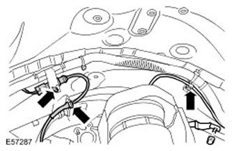
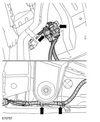
29. On the left side behind the headlight: Disconnect the frame harness electrical connector.
30. On the left side behind the front panel: Disconnect the 2 electrical connectors from the frame wiring harness.
31. On the left side behind the headlight: Release the 2 clips on the inside of the fender.
All cars
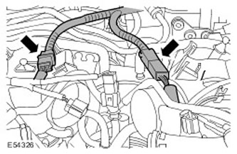
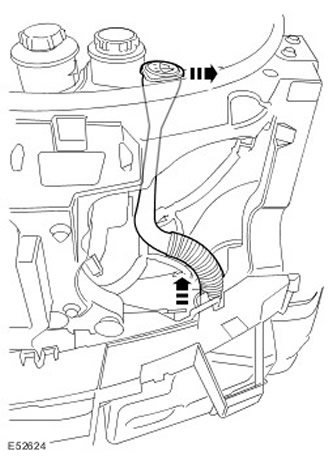
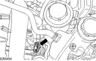
32. Disconnect the inlet and outlet cooling hoses of the fuel-powered auxiliary heater.
- Release two clamps.
33. Disconnect the filler neck of the windshield washer reservoir.
34. Disconnect two hoses from a broad tank.
- Release two clamps.
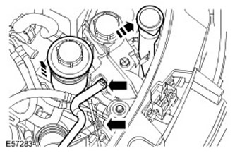
35. Remove the expansion tank.
- Turn out two bolts.
- Disconnect electrical connectors.
36. Disconnect the cooling fan electrical connector.
37. Disconnect the positive cable from the battery.
- Loosen the nut.
- Disconnect the positive cable from the battery.
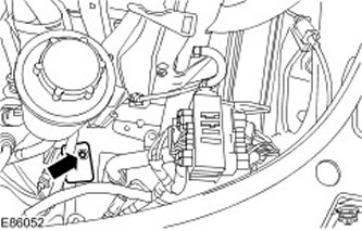
38. Disconnect the fuel line from the fuel fired heater heater.
39. Disconnect the three electrical connectors from the washer reservoir.
40.
NOTE: Mark the installation position.
Disconnect the two hoses from the washer pump.
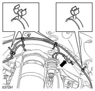
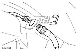
41. Left front side: Loosen the ABS sensor wire.
- Release two clamps.
- Disconnect electrical connectors.
- Release from four clips.
43. Left front side: Disconnect 2 air lines.
- Release 5 clips.
44. Left front side: Disconnect cables "masses" from the body frame.
- Loosen the nut.
- Disconnect 2 earth wires.
45.
CAUTION: Before disconnecting or removing components, clean the areas around the hinges and joints. Insert plugs into open connections to prevent dirt from entering them.
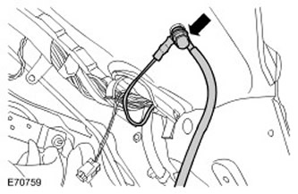
Left front side: Remove the brake pipe.
- Lay down a absorbent cloth to soak up spilled fuel.
- Disconnect the nipple connection.
- Remove clamp.
Vehicles manufactured before 01/2007
46. Disconnect the 3 electrical connectors from the frame wiring harness.
- Loosen the nut.
All cars
47. Right front: Disconnect the air suspension line from the harness clamp.
48. Right front: Release the ABS sensor wire.
- Release two clamps.
- Disconnect electrical connectors.
- Loosen the nut.
50.
CAUTION: Before disconnecting or removing components, clean the areas around the hinges and joints. Insert plugs into open connections to prevent dirt from entering them.
Right front: Remove the brake pipe.
- Lay down a absorbent cloth to soak up spilled fuel.
- Disconnect the nipple connection.
- Remove clamp.
51. Disconnect the electrical connector of the ambient temperature sensor.
- Release the clamp.
Vehicles manufactured before 01/2007
52. Disconnect the 2 electrical connectors from the frame wiring harness.
- Release two clamps.
All cars
53. Remove the molding of the right rear side panel of the body. For more information, refer to Rear Side Panel Molding (76.43.55)
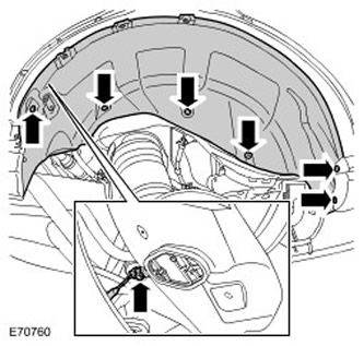
54. Remove the mudguard of the right rear wing.
- Remove five screws.
- Remove the snap ring.
- Disconnect electrical connectors.
- Repeat the above procedure on the other side of the vehicle.
55. Remove the rear bumper cover. For more information refer to Rear Bumper Cover (76.22.74)
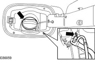
56. Release the fuel filler neck.
- Open the filler cap and remove the cap.
- Turn out a bolt.
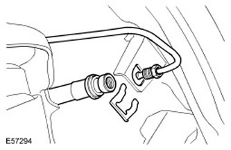
57.
CAUTION: Before disconnecting or removing components, clean the areas around the hinges and joints. Insert plugs into open connections to prevent dirt from entering them.
Rear right: Remove the brake pipe.
- Lay down a absorbent cloth to soak up spilled fuel.
- Disconnect the nipple connection.
- Remove clamp.
58. Left rear: Disconnect 2 electrical connectors from frame wiring harness.
59.
CAUTION: Before disconnecting or removing components, clean the areas around the hinges and joints. Insert plugs into open connections to prevent dirt from entering them.
Rear left: Remove the brake pipe.
- Lay down a absorbent cloth to soak up spilled fuel.
- Disconnect the nipple connection.
- Remove clamp.

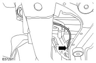
60.
CAUTION: Before disconnecting or removing components, clean the areas around the hinges and joints. Insert plugs into open connections to prevent dirt from entering them.
Rear left: Disconnect the air suspension air compressor intake line.
61.
CAUTION: Mark the installation position of the seal.
Disconnect the parking brake cable emergency release cable.
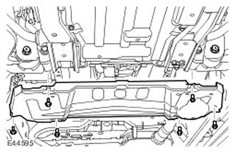
62. Remove the gearbox protection.
- Remove six bolts.
Vehicles with automatic transmission
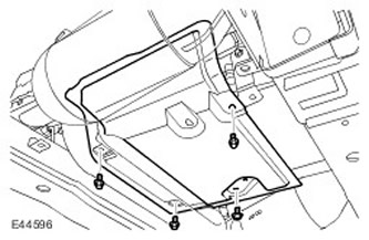
63. Remove the transmission heat shield.
- Turn out four bolts.
64. Release the selector lever cable.
- After securing the clamping sleeve with an additional wrench, loosen the locknut.
- Press the latch and release the cable.
All cars
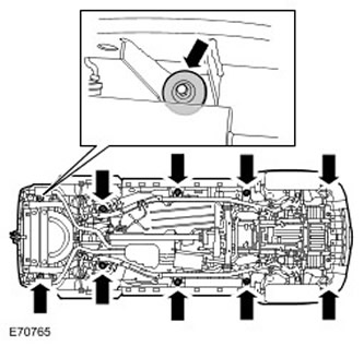
65. Turn out bolts of fastening of a support of a body.
- Remove 10 spacers.
66. Temporarily install wheel and tire assemblies.
- Tighten the wheel nuts.
- Lower the car on the lift.
WARNING: Do not work on or under a vehicle that is only supported by a jack. Always place secure supports under the vehicle.
WARNING: To prevent the body from becoming unstable when it is lifted from the solid frame, install tether straps to secure the vehicle.
NOTE: Mark the installation position of the body supports.
NOTE: Body supports are color coded.
With the help of an assistant, lift and support the body.
- Remove 10 body supports.
- With the help of an assistant, lift and support the body.

Installation
All cars
1.
CAUTION: Use new bolts.
WARNING: Make sure all components are free and not caught when lowering the body onto the subframe.
With the help of an assistant, place the body on the subframe.
- Install body mounts.
- With assistance, align the body supports with the subframe supports.
- Screw in the bolts, but do not tighten them all the way yet.
3.
WARNING: Do not work on or under a vehicle that is only supported by a jack. Always place secure supports under the vehicle.
Raise the car with a jack and install supports.
- Raise the vehicle with jack stands under the body subframe.
5. Remove wheels with tires.
Vehicles with automatic transmission
6. Connect the gear selection cable.
All cars
7. Attach the parking brake emergency release cable.
- Clean the contact surfaces of the elements.
NOTE: Remove and discard plugs.
Rear left: Connect the air suspension air compressor intake line.
- Clean the contact surfaces of the elements.
- Clean the contact surfaces of the elements.
- Establish the brake pipeline.
- Reinstall the clamp.
- Tighten the nipple connection of the brake pipeline with a force of 16 Nm.
11. Right rear: Connect the brake line.
- Clean the contact surfaces of the elements.
- Establish the brake pipeline.
- Reinstall the clamp.
- Tighten the nipple connection of the brake pipeline with a force of 16 Nm.
- tighten bolt (tightening torque 10 Nm).
14. Establish an overlay of a back bumper. For more information refer to Rear Bumper Cover (76.22.74)
15. Establish a molding of the right back side panel of a body. For more information, refer to Rear Side Panel Molding (76.43.55)
Vehicles manufactured before 01/2007
16. Connect 3 electrical connectors to frame wiring harness.
- Lock three clamps.
17. Left front side: Connect the brake line.
- Clean the contact surfaces of the elements.
- Establish the brake pipeline.
- Fasten the clamp.
- Tighten the nipple connection of the brake pipeline with a force of 16 Nm.
- Connect ground cables.
- tighten the nut (tightening torque 25 Nm).
20. Left front: Connect the brake pad wear sensor electrical connector.
- Fasten the fasteners.
- Connect the electrical connector.
- Fasten the fasteners.
23.
NOTE: Reinstall the parts in their original positions.
Connect the washer pump hoses.
24. Connect the electrical connectors of the washer reservoir.
25. Right front: Attach the subframe wiring harnesses.
- Secure with 2 clips.
- Clean the contact surfaces of the elements.
- Establish the brake pipeline.
- Fasten the clamp.
- Tighten the nipple connection of the brake pipeline with a force of 16 Nm.
- Connect the electrical connector.
- Fasten with clips.
29. Right front: Connect the engine ground wire to the body.
- tighten the nut (tightening torque 25 Nm).
- Connect the electrical connector.
- Fasten the clamp.
31. Connect the 2 electrical connectors to the frame wiring harness.
- Lock two clamps.
32. Connect the cooling hoses of the fuel-powered auxiliary heater.
- Lock the clamps.
34. Install the hood latch panel. For more information refer to Hood Latch Panel (76.16.22)
Vehicles manufactured since 01/2007
35. Pass the frame wiring harness through the front fender.
36. On the left side behind the headlight: Connect the frame harness electrical connector.
37. On the left side behind the front panel: Connect the 2 electrical connectors to the frame wiring harness.
38. On the left side behind the headlight: Attach 2 clips to the inside of the fender.
All cars
39. Install the expansion tank of the cooling system.
- Connect the electrical connector.
- Tighten the bolts with tightening torques of 10 Nm.
- Fasten with clips.
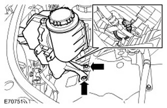
42. Fix a tank of the amplifier of a steering.
- Position and secure on the support bracket.
44. Install mudguards on both front fenders. For more information refer to Fender Mudguard (76.10.48)
45. Install the lower wing molding.
- Engage 2 clips.
- Repeat the above procedure on the other side of the vehicle.
NOTE: Remove and discard plugs.
Connect the high and low pressure air conditioner lines.
- Clean the contact surfaces of the elements.
- Install new o-rings.
- Fasten the wire harness clamp.
- Attach the glow plug wiring harness.
Vehicles manufactured since 01/2007
50. Connect the electrical connector of the engine coolant temperature sensor (EATING).
- Fasten the clamp.
51. Attach the cassettes and wiring harnesses of the engine and transmission.
52. Connect the two electrical connectors of the engine wiring harness.
53. Connect the two electrical connectors of the transmission wiring harness.
54. Install the engine and transmission harness cassettes.
55. Install the extra battery tray. For more information, refer to Additional Battery Shelf (76.10.31)
56.
NOTE: Make sure the wheels are in the straight ahead position.
Attach the lower steering column shaft.
- Clean the contact surfaces of the elements.
- Screw in a new locking bolt and tighten to 25 Nm.
- Fasten with clips.
NOTE: Remove and discard plugs.
Connect the brake booster vacuum hose.
59. Install the battery tray.
- Tighten nuts (tightening torque 12 Nm).
61. Install the side wall of the battery compartment.
- Fasten with clips.
- Connect the positive battery cable to the BJB.
- tighten the nut (tightening torque 25 Nm).
- Install the sealing ring.
- Install the BJB cover.
63. Install the floor console top panel. For more information, refer to Floor Console Top Panel (76.25.11)
64. Install the shift lever support bracket.
- Tighten the bolts (tightening torque 25 Nm).
- Attach the protective cover.
- Install the sound deadening pad.
65. Install the air filter assembly. For more information refer to Air Filter (19.10.01)
66. Connect the wire "masses" battery. For more information refer to Specification.
67. Add coolant to the cooling system and remove air from it. For more information, refer to Draining/Filling Coolant and Bleeding the Cooling System (26.10.01)
68. Refill the air conditioner. For more information, refer to Refrigerant Recovery, Vacuuming and Charging the Air Conditioning System (A/C) (82.30.02)
69. Bleed the brake system. For more information, refer to Bleeding the Brake System (70.25.02)
70. Install wheels with tires.
- Tighten nuts (tightening torque 140 Nm).
71. Adjust the selector cable. For more information, refer to Selector Lever Cable Adjustment (44.30.04)
Comments on this article