Contents: Removal ⇩ Installation ⇩
Removal
NOTE: This procedure requires the body to be removed from the body subframe. This procedure can only be performed on a 2-post lift.
1.
CAUTION: Do not work on a vehicle supported solely by a jack. Always place reliable supports under the vehicle.
Raise and support the vehicle.
2. Remove the wheels.
3. Disconnect the ground cable from the battery. For more information, refer to Specification.
4. Drain the coolant. For more information, refer to Draining/Filling Coolant and Bleeding the Cooling System (10/26/01)
5. Discharge the refrigerant. For more information, refer to Refrigerant Recovery, Evacuation, and Charging of the Air Conditioning (A/C) System (82.30.02)
6. Remove the air cleaner assembly. For more information, refer to Air Cleaner (10/19/01)
7. Remove the TCM. For more information, refer to Four-Wheel Drive (4WD) Control Module (41.30.01)
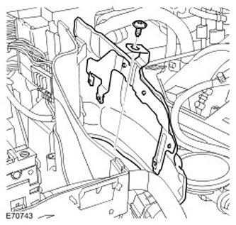
8. Remove the right upper engine compartment heat shield.
- Remove the screw.
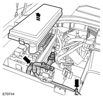
9. Disconnect the positive cable from the battery.
- Remove the BJB cover.
- Unscrew the nut.
- Remove the sealing sleeve.
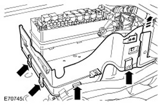
10. Remove the side wall of the battery box.
- Release the four clamps.
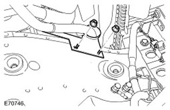
12. Release the positive battery cable bracket.
- Unscrew the two nuts.
13. Release and disconnect the two electrical connectors from the engine wiring harness.
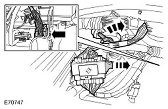
14. Release and disconnect the two electrical connectors on the gearbox.
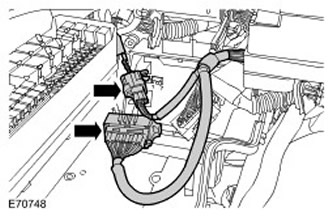
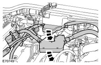
15. Release the wiring harness bundles on the engine and gearbox and place them to the side.
- Release the two clamps.
16. Remove the mudguards from both front fenders. For more information, refer to Fender Mudguard (76.10.48)
17. Remove the lower fender molding.
- Release the two clamps.
- Repeat the above procedure on the other side.
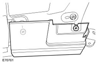
18. Remove the front bumper cover. For more information, refer to Front Bumper Cover (76.22.72)
19. Remove the lower radiator air deflector.
- Remove the three clamps.
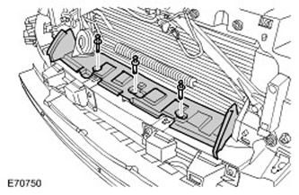
20. Remove the electronic stability control switch assembly. For more information, refer to Suspension and Handling Optimization Switch (86.65.11)
21. Release the power steering fluid reservoir from the bracket.
22. Disconnect the filler neck of the windshield washer reservoir
23. Disconnect the two hoses from the expansion tank.
- Release the two clamps.
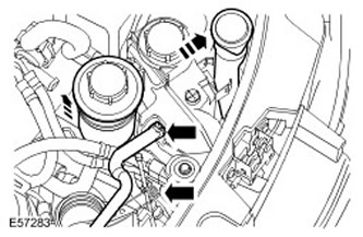
24. Remove the expansion tank.
- Disconnect the electrical connector.
- Remove two bolts.
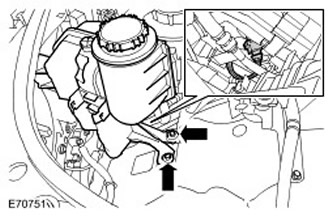
25.
CAUTION: Before disconnecting or removing components, ensure that the area around mating surfaces and connections is clean and dry. Plug open connections to prevent contamination.
Disconnect the brake booster vacuum hose.
- Release the clamp.
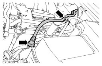
26.
CAUTION: Before disconnecting or removing components, ensure that the area around mating surfaces and connections is clean and dry. Plug open connections to prevent contamination.
Disconnect the low pressure line of the air conditioning compressor.
- Discard the oil seal.
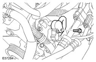
27.
CAUTION: Immediately plug all refrigerant lines to prevent dirt and moisture from entering.
Disconnect the high pressure line from the air conditioner condenser.
- Discard the oil seal.
- Squeeze the two clamps.
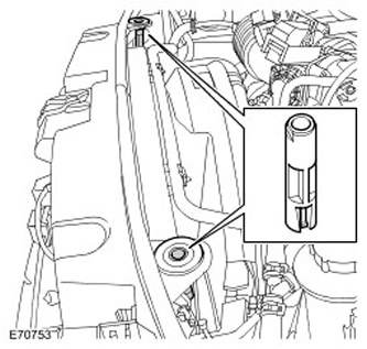
29. Disconnect the two heater coolant hoses.
- Release from two clamps.
- Release the clamps.
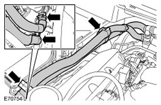
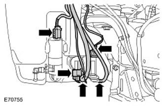
31. Disconnect the three electrical connectors from the washer reservoir.
32.
NOTE: Mark the installation position.
Disconnect the two hoses from the washer pump.
33. Disconnect the outside air temperature sensor wiring harness.
- Release the clamp.
- Disconnect the electrical connector.
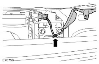
34. Right front: Release the air suspension line from the wiring harness clamp.
35. Right front: Release the ABS sensor wire.
- Release the two clamps.
- Disconnect the electrical connector.
- Unscrew the nut.
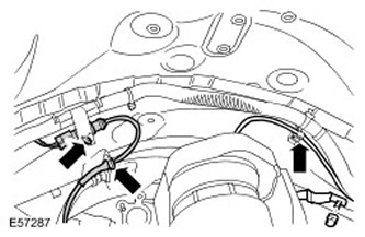
37. Right Front: Disconnect the two electrical connectors of the body wiring harness.
- Disconnect the two electrical connectors.
- Release the two clamps.
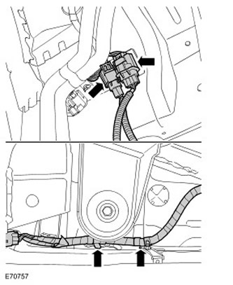
39.
CAUTION: Before disconnecting or removing components, ensure that the area around mating surfaces and connections is clean and dry. Plug open connections to prevent contamination.
Right front: Release the brake line.
- Place an absorbent cloth underneath to collect any leaking liquid.
- Disconnect the nipple connection.
- Remove the clamp.
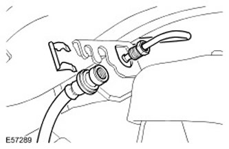
40. Left front side: Release the ABS sensor wire.
- Release the two clamps.
- Disconnect the electrical connector.
- Release from four clamps.
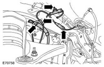
42. Left front side: Release the two air ducts.
- Release from five clamps.
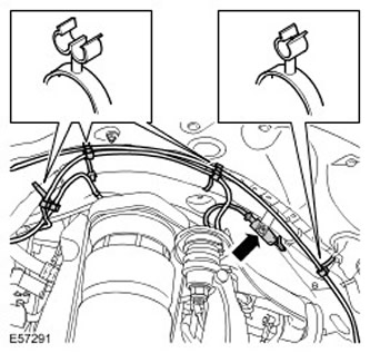
43. Left front side: Remove the engine compartment heat shield.
- Unscrew the three nuts.
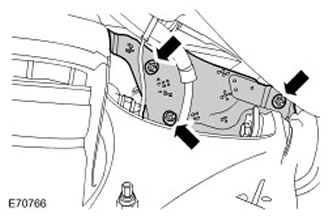
44. Disconnect the lower steering column shaft from the steering column.
- Remove and discard the Torx bolt.
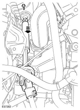
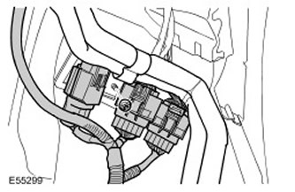
45. Left front side: Disconnect the three electrical connectors of the body wiring harness.
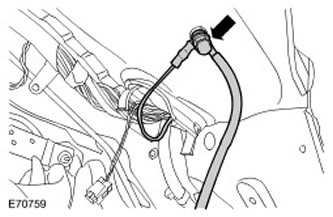
46. Left Front Side: Release the integrated ground wire on the body subframe.
- Unscrew the nut.
- Release the two ground wires.
47.
CAUTION: Before disconnecting or removing components, ensure that the area around mating surfaces and connections is clean and dry. Plug open connections to prevent contamination.
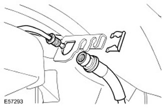
Left front side: Release the brake line.
- Place an absorbent cloth underneath to collect any leaking liquid.
- Disconnect the nipple connection.
- Remove the clamp.
48. Remove the rear fender moldings. For more information, refer to Rear Side Panel Molding (76.43.55)
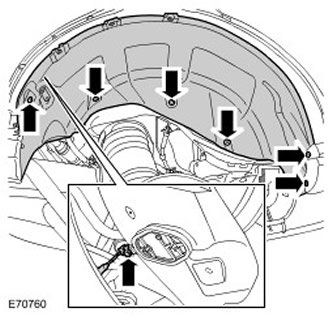
49. Remove the right rear fender splash guard.
- Remove five screws.
- Remove the stopper.
- Disconnect the electrical connector.
- Repeat the above procedure on the other side.
50. Remove the rear bumper cover. For more information, refer to Rear Bumper Cover (76.22.74)
51. Remove the fuel filler cap. For more information, refer to Fuel Filler Cap Assembly (19.55.04)
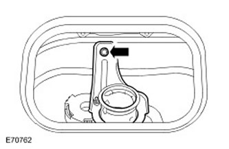
52. Release the fuel tank filler neck.
- Remove the bolt.
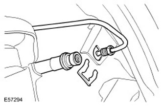
53.
CAUTION: Before disconnecting or removing components, ensure that the area around mating surfaces and connections is clean and dry. Plug open connections to prevent contamination.
Right rear: Disconnect the brake line.
- Place an absorbent cloth underneath to collect any leaking liquid.
- Disconnect the nipple connection.
- Remove the clamp.
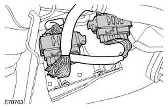
54. Left rear: Disconnect the two electrical connectors of the body wiring harness.
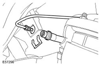
55.
CAUTION: Before disconnecting or removing components, ensure that the area around mating surfaces and connections is clean and dry. Plug open connections to prevent contamination.
Left rear: Disconnect the brake line.
- Place an absorbent cloth underneath to collect any leaking liquid.
- Disconnect the nipple connection.
- Remove the clamp.
56.
CAUTION: Before disconnecting or removing components, ensure that the area around mating surfaces and connections is clean and dry. Plug open connections to prevent contamination.
Left Rear: Disconnect the air suspension air compressor inlet line.
- Raise the car on a lift.
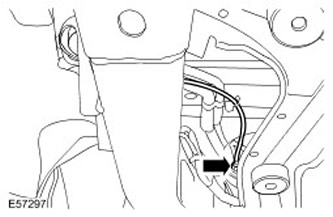
57.
CAUTION: Mark the installation position of the seal.
Disconnect the parking brake emergency release cable.
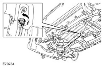
58. Remove the lower gearbox guard.
- Remove six bolts.
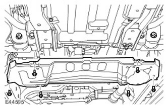
59. Remove the gearbox heat shield.
- Remove four bolts.
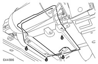
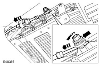
60. Release the gear selector cable.
- While holding the clamping sleeve with the second key, release the lock nut.
- Press the latch and release the cable.
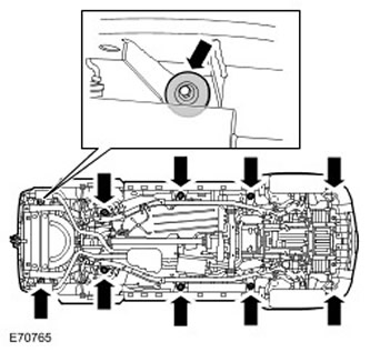
61. Remove the body support mounting bolts.
- Remove 10 spacer washers.
62. Temporarily install the wheels.
- Lower the car onto the lift.
- Tighten the wheel nuts.
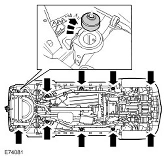
NOTE: Mark the installation position of the body supports.
NOTE: The body supports are marked with different colors.
Raise and support the body.
- Remove 10 body supports.
Installation
1.
NOTE: The body supports are marked with different colors.
NOTE: Install the elements according to their original position.
Install the body supports.
- Clean the mating surfaces of the elements.
CAUTION: Carefully lower the body onto the body frame. Make sure that no components are pinched. Pay particular attention to loose connections and the radiator area.
Install the body onto the body frame.
- Clean the mating surfaces of the elements.
- With outside help, align the body supports with the subframe supports.
- Install spacer washers.
- Screw in the bolts, but do not tighten them completely yet.
- Raise the vehicle using supports located under the body subframe.
(Original version of the article on the website: «www.lrman.ru»)
4. Tighten the subframe-to-body mounting bolts to 133 Nm.
5. Connect the gear selector cable.
6. Secure the parking brake emergency release cable.
- Clean the mating surfaces of the elements.
- Clean the mating surfaces of the elements.
- Secure the clamp.
- Lower the car onto the lift.
- Clean the mating surfaces of the elements.
- Install the brake line.
- Install the clamp.
- Tighten the brake pipe union to 16 Nm.
10. Right rear: Connect the brake line.
- Clean the mating surfaces of the elements.
- Install the brake line.
- Install the clamp.
- Tighten the brake pipe union to 16 Nm.
- Tighten the bolt to 10 Nm.
13. Install the rear bumper cover. For more information, refer to Rear Bumper Cover (76.22.74)
14. Install the mud flaps on both rear fenders.
15. Install both rear fender moldings. For more information, refer to Rear Side Panel Molding (76.43.55)
16. Left front side: Connect the brake line.
- Clean the mating surfaces of the elements.
- Install the brake line.
- Secure the clamp.
- Tighten the brake pipe union to 16 Nm.
- Connect the ground wires.
- Tighten the nut to 25 Nm.
19.
NOTE: Set the steering to the straight-ahead position.
Connect the lower steering column shaft.
- Clean the mating surfaces of the elements.
- Screw in a new self-locking bolt and tighten it to 25 Nm.
- Tighten the nuts to 10 Nm.
22. Left front side: Connect the brake pad wear sensor electrical connector.
- Secure with clamps.
- Connect the electrical connector.
- Secure with clamps.
25. Right Front: Secure the body frame wiring harness.
- Secure with two clamps.
- Clean the mating surfaces of the elements.
- Install the brake line.
- Secure the clamp.
- Tighten the brake pipe union to 16 Nm.
- Tighten the nut to 25 Nm.
- Connect the electrical connector.
- Secure the clamps.
30. Connect the outside air temperature sensor wiring harness.
- Connect the electrical connector.
- Secure the clamp.
NOTE: Install the elements according to their original position.
Connect the washer pump hoses.
32. Connect the electrical connectors of the washer reservoir.
33.
CAUTION: Lubricate new seals with clean compressor oil.
Connect the low pressure line of the air conditioning compressor.
- Clean the mating surfaces of the elements.
- Install a new O-ring.
- Tighten the bolt to 6 Nm.
CAUTION: Lubricate new seals with clean compressor oil.
Connect the high pressure line of the air conditioner condenser.
- Clean the mating surfaces of the elements.
- Install a new O-ring.
- Tighten the bolt to 6 Nm.
- Clean the mating surfaces of the elements.
- Connect the electrical connector.
- Tighten the bolts to 10 Nm.
- Secure the clamps.
39. Reinstall the power steering fluid reservoir.
- Position and secure to support bracket.
41. Install the lower radiator air deflector.
- Secure with three clamps.
43. Install the mudguards on both front fenders. For more information, refer to Fender Mudguard (76.10.48)
44. Install the lower fender molding.
- Secure with two clamps.
- Repeat the above procedure on the other side.
46. Connect the two electrical connectors of the engine wiring harness.
47. Connect the two electrical connectors of the transmission wiring harness.
48. Install the engine and transmission wiring harnesses.
49. Install the TCM. For more information, refer to Four-Wheel Drive (4WD) Control Module (41.30.01)
50. Install the battery box side wall protruding panel.
51. Install the side wall of the battery box.
- Secure the clamps.
- Screw in the screw.
- Connect the positive battery cable to the BJB.
- Tighten the nut to 25 Nm.
- Install the sealing bushing.
- Install the BJB cover.
- Secure the clamps.
- Secure with clamps.
57. Connect the ground cable to the battery. For more information, refer to Specification.
58. Fill the cooling system with coolant and bleed the systems. For more information, refer to Draining/Filling Coolant and Bleeding the Cooling System (10/26/01)
59. Recharge the A/C system. For more information, refer to Refrigerant Recovery, Evacuation, and Charging of the Air Conditioning (A/C) System (82.30.02)
60. Bleed the brake system. For more information, refer to Bleeding the Brake System (70.25.02)
61. Install the wheels.
62. Install the electronic stability control switch assembly. For more information, refer to Suspension and Handling Optimization Switch (86.65.11)
63. Adjust the gear selector cable. For more information, refer to Adjusting the Gear Selector Cable (44.30.04)
64. Install the transmission heat shield.
- Tighten the bolts to 10 Nm.
- Tighten the bolts to 10 Nm.
Comments on this article