- Range switch signal
- Selected range sensor signal
- Transfer case motor temperature signal
- Transfer case motor position sensor signal
- CAN bus messages
- Gear Position Sensor Signal (only for manual transmission)
- Gearbox Output Speed Sensor Signal (only for manual transmission).
CAN bus messages
The CAN bus is a high-speed data communication network that links the various control modules in a vehicle. CAN network control modules exchange multiple messages, allowing for more complex control without increasing system complexity. To increase the efficiency of the exchange, data in the network is transmitted in packets and ranked depending on the urgency and importance of the message. The CAN bus is a two-wire line, the wires of which are twisted together to reduce electromagnetic interference (noise), generated by bus messages. For more information refer to Communications Network (418-00)
The transfer case control module is connected to the CAN bus and controls the operation of the transfer case using CAN·messages from other network control units. The main data sent to the transfer case control module are: wheel speeds, vehicle acceleration, engine torque and speed, current gear for automatic transmission, temperature information, vehicle configuration data, final drive ratios, and terrain mode data response™.
The following symptoms may indicate a CAN bus failure:
- Inability to switch from high range to low range or vice versa
- Inoperability of the low range indicator lamp on the instrument panel
- Warning messages or indicators displayed on the instrument panel
Gear position sensor (only for manual transmission)
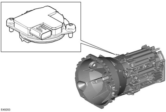
The transfer case control module determines the current transmission gear based on position information from the manual transmission gear position sensor. This information is distributed over the CAN bus for display on the instrument panel and for use by other vehicle systems. Vehicles equipped with an automatic transmission use similar messages propagated by the transmission control module (TCM). Vehicles equipped with a manual transmission have a tuning function that compares the position data provided by the sensor with a gear ratio calculated from the ratio of the engine speed to the transmission output shaft. The gearbox setting is done after the vehicle is assembled. If a new gearbox is installed during the operation of the car, the tuning algorithm should ensure that it is tuned to the characteristics of the new gearbox.
The instrument panel displays the selected gear as determined by the transfer case. The transfer case also uses this information before attempting a range shift to confirm that the vehicle is in neutral. For more information refer to Manual Transmission (308-03)
Manual Transmission Output Shaft Speed Sensor
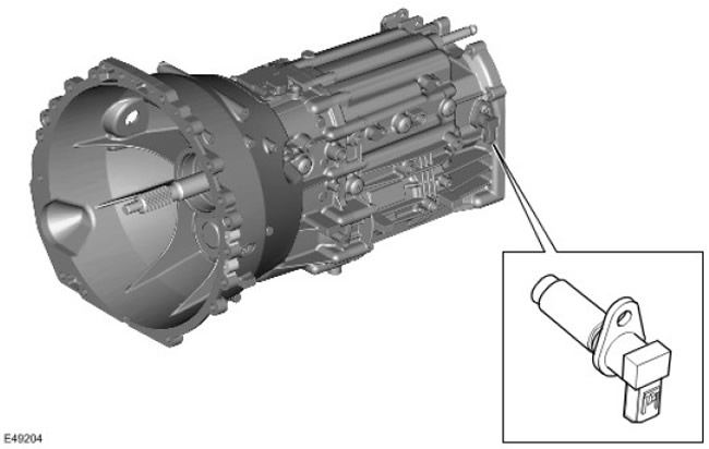
The output shaft speed sensor is located at the rear of the transmission and measures the speed of the transmission output shaft.
The design of the transfer case allows the ranges to be changed while the vehicle is moving, ensuring that the transmission shaft speed and the preset thresholds determined by the control module are matched. Based on the gearbox output speed and the vehicle wheel speeds, the control module calculates the optimum synchronization time. For more information refer to Manual Transmission (308-03)
Range select switch
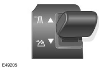
The range select switch is located on the center console behind the main shift lever. The switch is a 3-position momentary switch with a central spring. To select a high range, the lever is moved forward, and to select a low range - back.
The switch has a housing, inside of which there is a sliding contact. Sliding the switch to the high or low range position provides a momentary connection to the 12V circuit using one of the two microswitches located at either end of the range select switch. Microswitches correspond to high and low range positions.
The transfer case control module receives this momentary signal and selects the desired range.
When the switch is released, a spring moves the selector lever to the center position.
Selected Range Sensor
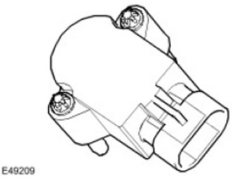
The selected range sensor converts the turn of the range fork into a PWM signal. Each range has its own PWM signal. The transfer case control module checks for this signal and informs the driver via the instrument panel and range select switch LEDs whether or not the range change is complete.
The selected range sensor is connected to the transfer case control module using a three-pin connector.
Comments on this article