Contents: Terrain Response™ System ⇩ Work in high range ⇩ Working in low range ⇩ Switching ranges while driving ⇩ Range switching order (only for cars…⇩ Range switching order (only for…⇩ Transfer case control diagram ⇩
The transfer case range is selected using a switch located on the center console behind the main gearshift lever. The range can only be changed when the gearshift lever is in neutral (position 'N' in cars with an automatic transmission). The accelerator pedal must be released during the range change process.
If a range shift command is issued but the transmission shift lever is not in the neutral position ('N' or 'P' position on vehicles with an automatic transmission), the message center field on the instrument cluster (if there is one) the message 'SELECT NEUTRAL FOR RANGE CHANGE' will appear (select neutral position to change range).
NOTE: If the transmission shift lever is in the 'P' position on vehicles with an automatic transmission, the range will not change, but the 'SELECT NEUTRAL FOR RANGE CHANGE' message will (select neutral position to change range) will not appear in the message center field.
When low range is selected, the low range 'mountain' symbol will flash while the range change is in progress and remain lit when the range change is complete. To confirm that the range change is complete, in the instrument cluster message center field (if there is one) the message 'LOW RANGE' is displayed for about 3 seconds (low range), and then the instrument cluster emits a beep. In cars with an automatic transmission, only 'D' and 'Manual mode' are available. (manual mode), 'Sport mode' (sports mode) not available for selection.
If high range is selected, the low range 'mountain' symbol will flash during the range change and will go out after the range change. To confirm that the range change is complete, in the instrument cluster message center field (if there is one) the message 'HIGH RANGE' is displayed for about 3 seconds (high range), and then the instrument panel emits a beep.
The design of the transfer case allows switching ranges while the vehicle is moving within the following limitations:
- Shifting from high to low range - speed should not exceed 40 km/h in cars with automatic transmission and 20 km/h in cars with manual transmission
- Shifting from low to high range - speed should not exceed 60 km/h.
Shifting at a speed of less than 3 km/h is considered by the transfer case control module as static shifting. (shifting in a stationary vehicle). In vehicles with an automatic transmission, the driver must then use the brake pedal to lock the selector lever to enable the gearshift lever to be moved from position 'N' to position 'D' after completing the range change.
High range should be used for normal road driving and off-road driving in dry, level terrain. Low range may only be required for low-speed maneuvering, such as reversing a trailer, driving on rocky surfaces, or when steep, slippery inclines are required. Low range should also be used in extreme off-road conditions, where high range does not allow forward movement. Low range should not be used under normal driving conditions.
Terrain Response™ System
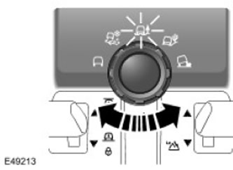
The Terrain Response™ system allows the driver to select a program that will provide the optimum parameters in terms of traction and dynamic performance for the current road conditions.
The system is controlled by a rotary switch located on the central console. The rotary switch allows you to select one of five programs:
- Special programs are disabled (normal road conditions)
- Grass/Gravel/Snow program (grass/gravel/snow).
- Mud/Ruts Program (mud/rut).
- Sand program
- Rock crawl program (slow movement on a rocky surface).
- Engine management system
- Automatic transmission (if available)
- Transfer case
- Rear differential lock (if available)
- Brake system
- Air suspension
Work in high range
In the high range, the primary torque generated by the gearbox is transmitted to the primary shaft of the transfer case. The synchronizer clutch connects the shaft directly to the differential housing. The differential distributes the torque between two axle gears. One axle gear has a splined connection and transmits torque to the rear output flange. The second axle gear is connected to the chain drive sprocket and transmits torque to the front output flange via the chain.
Working in low range
In the low range, the primary torque generated by the gearbox is transmitted to the primary shaft of the transfer case. The synchronizer clutch moves and connects the planetary carrier to the differential housing. In this state, the gearbox torque is transmitted to the planetary carrier via the sun gear of the planetary gear, as well as via the satellites and the satellite shafts. A ring gear of the planetary gear is fixed inside the housing, which provides a low range gear ratio of 2.93:1. Then, the torque goes through the synchronizer clutch to the differential housing, where it is divided between two half-axle gears. One half-axle gear has a splined connection and transmits torque to the rear output flange. The second half-axle gear is connected to the chain drive sprocket and transmits torque to the front output flange via the chain.
Switching ranges while driving
The driver has the ability to switch between low and high ranges both while driving and when the vehicle is stationary.
Pressing the range shift lever generates a request to change range. This lever is located on the center console behind the main gearshift lever. (to the side of him).
Moving the range selector lever toward the rear of the vehicle requests a shift from high to low range, and vice versa, moving the range selector lever toward the front of the vehicle requests a shift from low to high range. The range selector lever is spring-loaded in the center and is therefore not locked in the forward and rear positions.
The selected range is indicated by a green lamp (the "mountain" symbol) on the instrument panel and LEDs next to the range switching lever. The lamp is off in the high range, lights up in the low range and flashes during the range change. There are 2 LEDs next to the range switching lever: one for the high range, the other for the low range. During range switching, the LED of the newly selected range flashes.
The selected range is retained until the driver requests a shift. Thus, the high range is not automatically restored after the ignition is turned on and off.
Range switching order (only for cars with automatic transmission)
Before changing the range, the gearbox must be in neutral position, and the desired gear is selected only after the range change is completed. During the range change, the gearbox is locked in neutral position.
If you attempt to change range without placing the transmission in neutral, the request to change range will be ignored and the message in the instrument cluster message center field will be (if there is one) a message will appear asking you to select neutral.
The process of switching the range after accepting the corresponding request lasts no more than 1 second.
Shifting between ranges is only possible when the vehicle speed does not exceed the set limits. The maximum speed at which shifting from high to low range is possible is 40 km/h (25 mph) in vehicles with an automatic transmission and 20 km/h (12 mph) in vehicles with a manual transmission. The maximum speed at which shifting from low to high range is possible is 60 km/h (37 mph). If a range shift request is issued when the vehicle speed exceeds the limit, the request is rejected and the message in the message center field on the instrument cluster (if there is one) the message 'SLOW DOWN' is displayed (reduce speed).
Range switching order (only for vehicles with manual transmission)
Before changing the range, the gearbox must be in neutral, and the desired gear is selected only after the range change is completed. During the range change, the driver must not try to move the gearbox out of neutral. When the lever is moved out of neutral, the range change is stopped and can only be completed after the driver has reset the neutral position. This prevents damage to the transfer case mechanism.
The speed limit for shifting while driving in vehicles with a manual transmission is lower than that in vehicles with an automatic transmission, at approximately 20 km/h (12 mph) for shifting from high to low and 60 km/h (37 mph) for shifting from low to high. The lower limits are set to prevent damage to the vehicle if the driver attempts to select too low a gear after changing range.
Transfer case control diagram
NOTE: A = Wired; D = CAN bus
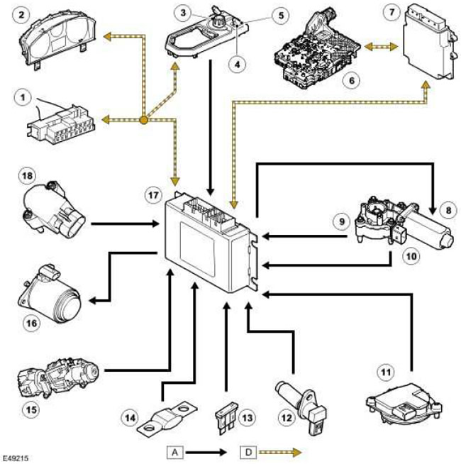
| Item name | Spare part catalog number | Description |
| 1 | - | Diagnostic connector |
| 2 | - | Instrument panel |
| 3 | - | Terrain Response™ System |
| 4 | - | Range selection switch |
| 5 | - | LED indicator of the selected range |
| 6 | - | Transmission Control Module (TCM) |
| 7 | - | Engine Control Module (ECM) |
| 8 | - | Transfer case electric motor |
| 9 | - | Temperature sensor |
| 10 | - | Hall sensors (for speed and direction) |
| 11 | - | Gear position sensor for manual transmission |
| 12 | - | Output shaft speed sensor |
| 13 | - | Fuse 24 ignition system power supply circuit |
| 14 | - | Fuse link of the battery constant power supply circuit |
| 15 | - | Ignition switch |
| 16 | - | Electromagnet |
| 17 | - | Transfer Case Control Module |
| 18 | - | Selected range sensor |
Comments on this article