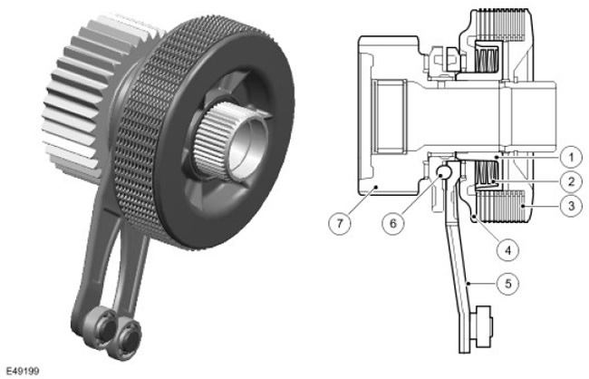
| Item name | Spare part number | Description |
| 1 | - | Clutch hub |
| 2 | - | Belleville springs |
| 3 | - | Clutch discs |
| 4 | - | Clutch piston |
| 5 | - | Motor levers |
| 6 | - | Ball locking mechanism |
| 7 | - | Star |
The multi-plate clutches of the center and rear differentials operate on the same principle. The multi-plate clutch prevents excessive slip of the differential and, as a result, maximizes the vehicle's tractive effort. This is fundamentally different from anti-slip control with braking, in which it is only possible to neutralize differential slip when the latter occurs.
A certain slip of the differential is necessary when cornering. It enables the vehicle to maintain stability when operating the anti-lock braking system (ABS). The transfer case control module receives commands from the driver using the vehicle's main controls and automatically sets the required slip torque for the differentials. The system is fully automated and does not require any special actions from the driver.
The multi-plate clutch actively manages the transmission of torque in the center differential and optimizes the torque distribution in the driveline. The clutch redistributes the transmission torque to the axle and wheels with more grip and prevents slipping of wheels with less grip.
The multi-plate clutch assembly consists of a sprocket (7), connected to the front semi-axial gear of the differential, the levers of the electric motor (5) with ball lock (6), coupling hub (1), which serves as a support for the clutch discs (3), Piston Clutch (4), providing friction between the clutch discs, and a package of cup springs (2), returning the clutch piston to its original position.
One set of friction discs is connected to the clutch hub; the other set - with a multi-plate clutch housing, which is welded to the center differential housing.
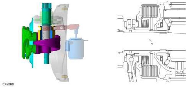
Engaging the multi-plate clutch
Transfer case motor levers in home position, multi-plate clutch disengaged
Transfer case motor in end position, multi-plate clutch engaged
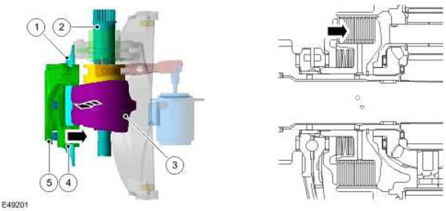
| Item name | Spare part number | Description |
| 1 | - | Clutch piston |
| 2 | - | motor shaft |
| 3 | - | Driven clutch disc |
| 4 | - | Motor levers |
| 5 | - | Ball locking mechanism |
When the clutch disc rotates (3) motor shaft (2) rotates relative to each other the levers of the electric motor (4). This relative motion acts on 5 balls (5) locking mechanism between 2 levers, causing a certain axial movement. Axial movement forces the clutch piston (1) create friction between the discs mounted on the clutch hub and the discs supported by the clutch housing on the differential cup. The friction force prevents the rotation of the differential, as a result of which the differential cup and the front differential side gear are blocked.
Comments on this article