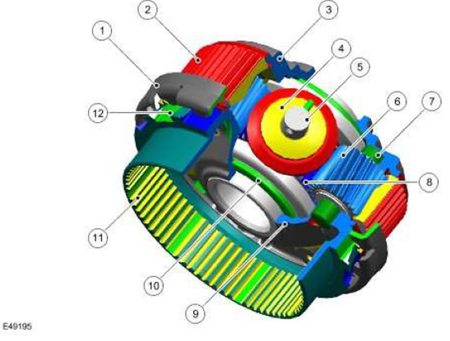
| Item name | Spare part catalog number | Description |
| 1 | - | Synchronizing ring and spring |
| 2 | - | Planetary gear crown gear |
| 3 | - | Differential cup |
| 4 | - | Satellites |
| 5 | - | Satellite axes |
| 6 | - | Planetary gear satellites |
| 7 | - | Planetary gear pinion axes |
| 8 | - | Sun gear of planetary gear |
| 9 | - | Differential cover |
| 10 | - | Differential axle gears |
| 11 | - | Multi-plate clutch housing |
| 12 | - | Teeth |
The center differential assembly is the main device of the transfer case. Torque is transmitted via the center differential cup and distributed between the differential gears and the front and rear output flanges. An integral part of the center differential assembly is the planetary set, designed to switch ranges.
This unit consists of 3 differential satellites (4) and their axles (5), uniformly distributed in the cup of the interaxle differential (3). The axles of the differential are rigidly fixed to the differential cup. Between the satellites there are 3 planetary gear satellites (6) with the corresponding axles (7). The sun gear of the planetary gear (8) and 2 differential axle gears (10) are located on the cup axis.
The planetary gear ring gear (2) is supported in both directions by the differential housing and the differential cover (9). The planetary gear ring gear is connected to the shift sleeve, which occupies the high or low range selection position.
The multi-plate clutch housing (11) is welded to the differential housing and provides support for the friction discs, the teeth (12) for engaging the high range, and the synchronizing ring and spring (1) of the "shift on the go" mechanism.
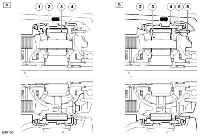
| Item name | Spare part catalog number | Description |
| A | - | High range position |
| B | - | Low range position |
| 1 | - | Teeth |
| 2 | - | Planetary gear satellites |
| 3 | - | Planetary gear crown gear |
| 4 | - | Shift bushing |
| 5 | - | Low range teeth |
| 6 | - | Rear carrier assembly |
When the high range is engaged, the shift sleeve (4) is connected to the differential cup via the teeth (1). In addition, the planetary gear crown gear (3) is connected to the differential cup. (via the shift sleeve) and planetary gear satellites (5) (by means of the planetary gear satellite axes). The planetary gears rotate as a set and thus turn the differential axle gear with a gear ratio of 1:1.
In the low range, the electric motor shifts the shift sleeve (4) in the direction of the low range teeth (5). The low range teeth together with the synchronizing ring and spring are attached to the rear carrier assembly (6). When the shift sleeve engages the low range teeth, the planetary gear crown gear (3) is fixed by the shift sleeve in a stationary state, and the planetary gear satellites (2) rotate the differential axle gears with a gear ratio of 2.93:1 via the planetary gear bolts.
Sequence of actions when turning on the high range
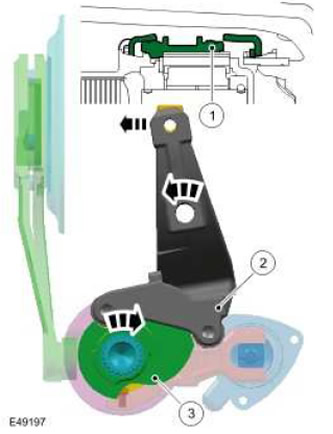
| Item name | Spare part catalog number | Description |
| 1 | - | Shift bushing |
| 2 | - | Range shift fork |
| 3 | - | Shift cam |
The electric motor shaft rotates the shift cam (3) to the high range position. The shift cam, in turn, moves the shift sleeve (1) to the high range position via the range shift fork. After synchronization, the planetary gear crown gear engages with the high range teeth on the differential cup via the shift sleeve. In this position, the input and output speeds are equal, which ensures a 1:1 gear ratio in the high range.
Sequence of actions when turning on the low range
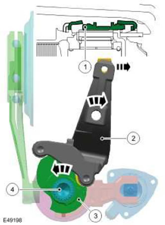
| Item name | Spare part catalog number | Description |
| 1 | - | Shift bushing |
| 2 | - | Range shift fork |
| 3 | - | Shift cam |
| 4 | - | Electric motor shaft |
The electric motor shaft (4) rotates the shift cam (3) to the low range position. The shift cam, in turn, moves the shift sleeve (1) of the interaxle differential assembly to the low range position via the range shift fork (2). After synchronization, the planetary gear ring gear engages with the low range teeth on the rear carrier assembly via the shift sleeve. As a result, the output speed is reduced with a gear ratio of 2.93:1.
Comments on this article