| Item name | Spare part number | Description |
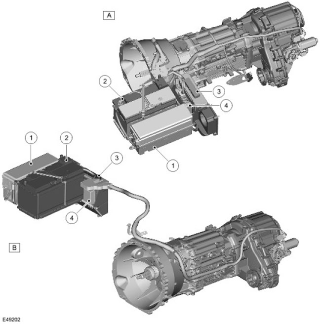
| A | - | Right Hand Drive |
| B | - | Left Hand Drive |
| 1 | - | Battery Junction Block (BJB) |
| 2 | - | Accumulator battery |
| 3 | - | The engine control unit (ECM) |
| 4 | - | Transfer case control module |
Control module connected to CAN bus (local area network of controllers) and controls the operation of the transfer case using messages received via the CAN bus from other LAN control modules.
When the ignition is turned off, the control module remembers the position of the transfer case motor.
The transfer case control module uses the same actuator for range shifting and center differential lock. The module utilizes actuator position feedback to provide smooth range shifting and progressive differential locking according to current driving conditions. Range shifting can be done while the vehicle is moving, provided the transmission is in neutral and the vehicle speed is below the speed required for the desired shift.
Input / output of all signals of the control module is carried out through 3 connectors. The module receives a constant supply voltage through a 30 A fusible link located in the battery distribution block (BJB), and the voltage of the ignition system through fuse 24, located in the central distribution block (CJB).
The control module uses several programmed switching maps to control the synchronization speed, resulting in a maximum switching time of approximately 1 second.
If the control module is replaced, the T4 diagnostic tool must be connected to the vehicle and the transfer box control module self-calibration must be run. These steps should also be performed after replacing the transfer case motor assembly.
Default strategy/emergency operation
When a malfunction occurs in the transfer case or transfer case control module, or one of the required input signals, such as the ground speed signal, fails, the control module registers a fault code and reacts in such a way as to preserve the maximum functionality of the system under the conditions of a particular malfunction. The following fault conditions are possible:
| Faulty state | System reaction | Driver warning |
| Functionality is not reduced | Diagnostic trouble code (DTC) is saved, but this does not affect the technical characteristics of the system | Absent |
| Clutch control blocked Temporary overheating | Off-road traction is reduced. | The driveline overheat warning light comes on or the message appears "CENTRE DIFF OVER TEMP REDUCE SPEED" on the message center screen |
| Clutch control blocked Permanent fault | Off-road traction is reduced. | The driveline malfunction indicator light comes on or the message "CENTRE DIFF FAULT TRACTION REDUCED" on the message center screen |
| Range switching prohibited | The system prevents the driver from changing the range | The driveline malfunction indicator light comes on or the message "TRANSMISSION RANGE CHANGE NOT AVAILABLE" on the message center screen |
| Transfer case sticking in neutral position | Transfer case sticking between high and low ranges resulting in wheel drive lockup | The low range indicator flashes and a message is displayed "APPLY HANDBRAKE (PARK BRAKE in USA and Canada) ". The message only appears when it is considered safe or necessary. For example, it is not displayed in normal driving mode. |
If the driveline has overheated, after the driveline cools down, clutch control will resume and the warnings will disappear. Maintenance is not required in this case.
If clutch control or range shifting is inhibited as a result of a permanent malfunction, the driver should seek technical assistance as soon as possible.
If a system malfunction has caused the transfer case to malfunction in neutral, the control module will continue to attempt to set the required range according to its program, or return to the original range after a predetermined number of attempts. If this is not possible and the low range lamp continues to flash, the driver should stop the vehicle and attempt to change range again with the vehicle stationary. After a number of unsuccessful attempts, turn off the ignition for 30 seconds, then start the engine and try again to switch the range in a stationary vehicle. The driver should seek technical assistance as soon as possible.
Transfer Case Control Module Connector Pin Table
Connector 1-C1319
| contact no | Description | Enter exit |
| 1 | Not used | - |
| 2 | Not used | - |
| 3 | CAN bus line low | Data (enter exit) |
| 4 | Range select switch - high level line | Entrance |
| 5 | Range select switch - line low | Entrance |
| 6 | High level CAN bus line | Data (enter exit) |
| 7 | Key interlock solenoid | Exit |
| 8 | LED High Line | Exit |
| 9 | LED low line | Exit |
Connector 2-C1854
| contact no | Description | Enter exit |
| 1 | CAN bus line low | Data (enter exit) |
| 2 | Not used | - |
| 3 | Ignition power | Entrance |
| 4 | High level CAN bus line | Data (enter exit) |
| 5 | Weight | - |
| 6 | Battery constant voltage | Entrance |
Connector 3-C1855
| contact no | Description | Enter exit |
| 1 | Hall sensor signal - A (direction) | Entrance |
| 2 | Hall sensor weight | - |
| 3 | Power supply for Hall sensors | Exit |
| 4 | Not used | - |
| 5 | temperature sensor | Entrance |
| 6 | Hall sensor signal - B (speed) | Entrance |
| 7 | Selector position sensor ground | - |
| 8 | Power supply 5 V encoder | Exit |
| 9 | Selector mode selector relay ground | - |
| 10 | Selector Position Sensor Signal | Entrance |
| 11 | X-axis signal of the gearbox position sensor | Entrance |
| 12 | Selector Mode Select Relay Supply | Exit |
| 13 | Transmission Position Sensor Y-Axis Signal | Entrance |
| 14 | Power supply for manual transmission output shaft speed sensor | Exit |
| 15 | Power supply / mass of the electric motor | Enter exit |
| 16 | Manual Transmission Output Shaft Speed Sensor Signal | Entrance |
| 17 | Mass of the speed sensor of the output shaft of the manual transmission | - |
| 18 | Power supply / mass of the electric motor | Enter exit |
Comments on this article