Transfer box housings
The front and rear crankcase assemblies are cast aluminum.
Front crankcase assembly
The input shaft and front output flange bearings are installed in the front crankcase assembly. It also has threaded holes for mounting the landing gear bushing, 2 lifting lugs and a breather cartridge for the transfer case breather tube. The breather tube balances the atmospheric pressure and the internal pressure of the transfer case.
Rear crankcase assembly
The rear crankcase assembly houses the rear output flange bearing, transfer box motor, and oil filler and drain plugs. Fins are cast on the rear crankcase to improve heat dissipation. In addition, the box number is stamped on the rear crankcase.
Oil pump
The oil pump is located in the front crankcase and provides lubrication to the bearings and rotating parts through cross-drilled holes in the input shaft. A flat, sectioned clutch on the input shaft drives the pump rotor while the pump stator is secured to the front crankcase assembly. Connected to the pump is a tube leading to a low suction area at the bottom of the 2 crankcase assemblies. In the suction area of the pump there is a magnet to collect metal particles.
Chain drive
The chain drive transfers torque from the center differential to the front output flange. 3/8 pitch chain" connects the transfer case input shaft sprocket to the sprocket on the front output flange. Since both sprockets have the same number of teeth, the speeds of these sprockets are the same.
Transfer box motor
High/low range switching and differential lock and torque distribution change (multi-plate clutch) driven by one electric motor. The motor solenoid provides switching of 2 functions, and the motor itself generates torque to perform them.
Transfer case motor position in clutch control mode
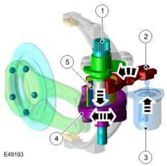
| Item name | Spare part number | Description |
| 1 | - | motor shaft |
| 2 | - | Electromagnet switch fork |
| 3 | - | Electromagnet |
| 4 | - | Driven clutch disc |
| 5 | - | Shift bushing |
The transfer case control module energizes the solenoid to engage the multi-plate clutch (3). The solenoid stem turns the solenoid switch fork (2), which engages the shift sleeve (5) with teeth on the clutch disc (4). Motor shaft rotation (1) through the shift sleeve is transmitted to the clutch disc.
This state corresponds to the normal operation of the transfer case. In this position, the range switching function is disabled and mechanically locked.
Transfer Case Motor Position in Range Mode
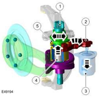
| Item name | Spare part number | Description |
| 1 | - | motor shaft |
| 2 | - | Electromagnet switch fork |
| 3 | - | Electromagnet |
| 4 | - | Shift bushing |
| 5 | - | drive cam |
To switch the transfer case range, the transfer case control module de-energizes the solenoid (3). The solenoid spring retracts the solenoid stem and turns the solenoid shift fork (2). Fork Engages Shift Bushing (4) with teeth on the range drive cam (5). Motor shaft rotation (1) transferred to the cam.
In this position, the multi-plate clutch is disengaged and the differential lock with torque redistribution is not possible. After the range shift is completed, the system returns to clutch control mode. In the event of a fault in the electrical circuit, the motor will default to this position.
Comments on this article