Contents: Air conditioning compressor ⇩ Capacitor ⇩ Receiver-dryer ⇩ Refrigerant pressure sensor ⇩ Thermostatic expansion valve ⇩ Evaporator ⇩ Refrigerant lines ⇩ Control scheme ⇩
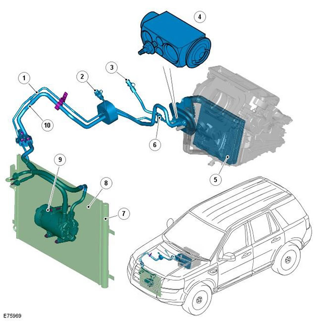
| Pos. | Spare part number | Name |
| 1 | - | High pressure main |
| 2 | - | High pressure service port |
| 3 | - | Low pressure service port |
| 4 | - | Thermostatic expansion valve |
| 5 | - | Evaporator |
| 6 | - | Refrigerant pressure sensor |
| 7 | - | Receiver-dryer |
| 8 | - | Capacitor |
| 9 | - | Air Conditioning (A/C) Compressor |
| 10 | - | Low pressure main |
The A/C system transfers heat from the interior to the outside air to provide the heater with dehumidified, cool air.
The A/C system is a sealed closed system that is filled with R134a refrigerant as a coolant. The refrigerant charge for i6 and TD4 vehicles weighs 730 g. Oil is added to the refrigerant to lubricate the internal components of the A/C compressor.
Although the A/C compressors on the i6 petrol and TD4 diesel engines are different, they are both variable flow units. The flow rate (refrigerant flow) is controlled to match the heat load of the evaporator.
The A/C system is controlled by the Automatic Temperature Control (ATC) module. For more information, refer to the chapter: Control Components (412-01 Climate Control, Description and Operation).
Air conditioning compressor
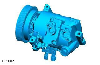
NOTE: A/C compressor shown is for i6 engine, same for TD4
The A/C compressor is driven by the engine accessory drive belt. It pumps refrigerant through the system, compressing the low-pressure, low-temperature vapor from the evaporator and sending the high-temperature, high-pressure compressed vapor to the condenser.
To prevent excess pressure from building up in the system, a relief valve is installed on the outlet side of the A/C compressor. The relief valve releases excess pressure into the engine compartment.
i6
I6 vehicles are equipped with a Zexel-Valeo KC-88 variable flow A/C compressor. The compressor flow is controlled by the engine control module (ECM) based on the current evaporator temperature and setpoint evaporator temperature signals received from the ATC module. Based on these values, the ECM calculates the desired compressor flow and sends a pulse width modulated signal to the compressor solenoid valve. The compressor solenoid valve is mounted on the rear of the compressor and interprets the PWM signal as a flow value and changes the position of the internal swash plate accordingly. For more information, refer to the chapter: Control Components (412-01 Climate Control, Description and Function).
ECM also reduces the supply of the A/C compressor to its minimum level if full throttle opening or the "kick down" function in the automatic transmission is requested. This feature is not available on vehicles intended for the Persian Gulf countries.
Compressor clutch engagement is controlled by the ECM. For more information, refer to chapter: Control Components (412-01 Climate Control, Description and Operation).
TD4
TD4 vehicles are equipped with a Visteon VS16 variable flow A/C compressor. The flow is controlled by a control valve that is built into the compressor. The control valve measures the refrigerant pressure at the compressor inlet and outlet and adjusts the angle of the internal swash plate accordingly.
NOTE: There is no external control of the A/C compressor swash plate angle. Therefore, compressor delivery is not controlled or metered by any external control.
Compressor clutch engagement is controlled by the ECM. For more information, refer to chapter: Control Components (412-01 Climate Control, Description and Operation).
Capacitor
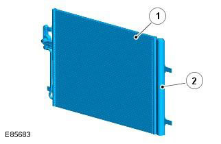
| Pos. | Spare part number | Name |
| 1 | - | Capacitor |
| 2 | - | Receiver-dryer |
The condenser is designed to convert the refrigerant vapor from the high-pressure gas phase obtained in the compressor into liquid and to remove heat from the refrigerant into the environment. The condenser is installed directly in front of the radiator of the cooling system. Two brackets located on the tanks serve to attach the condenser to the radiator tanks.
The condenser, the main elements of which are two tanks and a heat exchanger made of finned pipes located between them, belongs to the class of additional cooling condensers. Partitions in the tanks divide the condenser into four ascending sections (condensing) and two descending sections (additional cooling).
The right tank has ports for connecting the high pressure line from the A/C compressor and the low pressure line going to the evaporator.
Receiver-dryer
The receiver drier is built into the left condenser tank and removes solids and moisture from the refrigerant. It also functions as a liquid refrigerant storage tank to compensate for the effects of changing heat loads in the evaporator.
The refrigerant, entering the receiver-dryer, passes through a filter and a desiccant, then collects in the lower part of the receiver-dryer and returns to the condenser through the outlet pipe.
Refrigerant pressure sensor
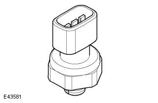
The refrigerant pressure sensor provides the ATC module with a pressure input signal from the high pressure side of the refrigerant system. The refrigerant pressure sensor is permanently wired to the ECM, which uses the signal to control the operation of the A/C compressor and calculate the additional engine load caused by A/C compressor operation. In addition, the ECM sends a high refrigerant pressure signal via the CAN bus to the central junction box (CJB). The CJB sends a signal via the medium speed CAN bus to the ATC module to increase the amount of recirculated air, if necessary.
The refrigerant pressure sensor is located in the line between the condenser and the expansion valve. For more information, refer to the chapter: Control components (412-01 Climate control, Description and principle of operation).
Thermostatic expansion valve
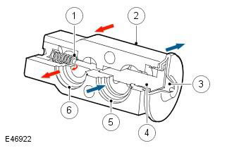
| Pos. | Spare part number | Name |
| 1 | - | Dosing valve |
| 2 | - | Frame |
| 3 | - | Diaphragm |
| 4 | - | Temperature sensor |
| 5 | - | Evaporator outlet channel |
| 6 | - | Inlet channel from the evaporator |
The thermostatic expansion valve is designed to regulate the amount of refrigerant entering the evaporator in accordance with the heat load from the air passing through the evaporator.
The thermostatic expansion valve of the block type is located behind the heater and is connected to the inlet and outlet ports of the evaporator. The aluminum body of the thermostatic expansion valve contains the inlet and outlet channels. A metering valve with a spring-loaded ball is installed in the inlet channel, and a temperature sensor is located in the outlet channel. The role of the temperature sensor is played by a thermal bulb connected to the cavity above the membrane. The lower part of the thermal bulb acts on the ball of the metering valve. The pressure above the membrane depends on the temperature at the outlet of the evaporator, which is transmitted through the capillary tube of the thermal bulb. The lower part of the membrane perceives the pressure at the outlet of the evaporator.
The liquid refrigerant flows through the metering valve into the evaporator. The constriction in the metering valve reduces the pressure and temperature of the refrigerant. This constriction also transforms the flow of liquid refrigerant into a thin stream, which helps improve the evaporation process. As the refrigerant passes through the evaporator, it absorbs heat from the air passing through the evaporator. When heated, the refrigerant evaporates and its pressure increases.
The temperature and pressure of the refrigerant at the outlet of the evaporator affect the thermal bulb and the membrane, which regulate the flow area of the metering valve and, accordingly, the amount of refrigerant passing through the evaporator. The warmer the air washing the evaporator, the more intensively the refrigerant evaporates and the greater the amount of refrigerant passes through the metering valve.
Evaporator
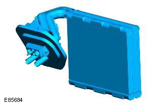
The evaporator is installed in the heater between the blower fan and the heater radiator and absorbs heat from the air coming either from outside (supply mode) or from the passenger compartment (recirculation mode). In the evaporator, the cold liquid refrigerant, which is under low pressure, turns into steam, absorbing a large amount of heat in the process of changing the state of aggregation.
Most of the moisture contained in the air that passes through the evaporator condenses and drains from the heater through a drain pipe under the bottom of the vehicle.
Refrigerant lines
The diameter of the refrigerant lines in different parts of the air conditioning system circuit changes to maintain equal refrigerant flow rates in accordance with two pressure and temperature regimes. The refrigerant with low pressure and temperature flows through large-diameter lines, and the heated refrigerant with high pressure flows through smaller-diameter lines.
The low pressure line to the A/C compressor and the high pressure line from the condenser use nylon lined low permeability rubber hoses. The remainder of the refrigerant lines are steel.
For servicing the system, low and high pressure ports are provided in the refrigerant lines.
Control scheme
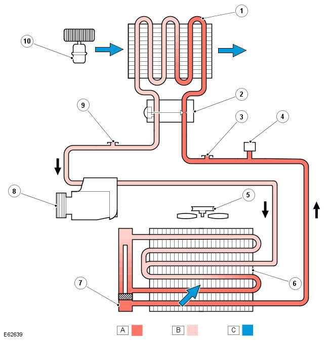
NOTE: A = Liquid refrigerant; B = Refrigerant vapor; C = Air flow
| Pos. | Spare part number | Name |
| 1 | - | Evaporator |
| 2 | - | Thermostatic expansion valve |
| 3 | - | High pressure service port |
| 4 | - | Refrigerant pressure sensor |
| 5 | - | Engine cooling fan |
| 6 | - | Capacitor |
| 7 | - | Receiver-dryer |
| 8 | - | A/C compressor |
| 9 | - | Low pressure service port |
| 10 | - | Cooling fan |
To achieve the heat transfer effect, forced circulation of the refrigerant is carried out, which undergoes a change in the aggregate state twice. During each change in the aggregate state, the greatest absorption or release of heat occurs.
Low pressure/low temperature side - from the expansion valve, through the evaporator to the compressor. The pressure and temperature of the refrigerant decreases in the expansion valve, and then in the evaporator the refrigerant changes its state of aggregation, passing from liquid to vapor, which is accompanied by the absorption of heat.
High pressure/high temperature side - from the compressor, through the condenser and receiver-dryer to the expansion valve. The pressure and temperature of the refrigerant increases as it passes through the compressor, then heat is released and the refrigerant changes from a vapor to a liquid in the condenser.
The A/C system is controlled by the Automatic Temperature Control (ATC) module. For more information, refer to the chapter: Control Components (412-01 Climate Control, Description and Operation).
Comments on this article