Contents: ATC module ⇩ Compressor solenoid valve ⇩ Refrigerant pressure sensor ⇩ Evaporator temperature sensor ⇩ Interior temperature sensor ⇩ Humidity sensor in the cabin ⇩ Outside air temperature sensor ⇩ Solar radiation sensor ⇩ Pollution sensor ⇩
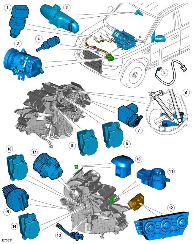
| Pos. | Spare part number | Name |
| 1 | - | Refrigerant pressure sensor |
| 2 | - | In-cabin humidity sensor (if available) |
| 3 | - | Air Conditioning (A/C) Compressor (i6 Engine Shown) |
| 4 | - | Engine Coolant Temperature (ECT) Sensor |
| 5 | - | Outside air temperature sensor |
| 6 | - | Air intake stepper motor |
| 7 | - | Pollution sensor (if available) |
| 8 | - | Stepper motor for supplying air to the windshield (de-icing) |
| 9 | - | Stepper motor of the right mixing temperature flap |
| 10 | - | Solar radiation sensor |
| 11 | - | Cabin air temperature sensor |
| 12 | - | Temperature Control Module (ATC) |
| 13 | - | Evaporator temperature sensor |
| 14 | - | Stepper motor of the left mixing temperature flap |
| 15 | - | Blower Motor Control Module |
| 16 | - | Stepper motor for air supply to face/footwell |
| 17 | - | Electric blower fan |
The climate control system combines the heating, ventilation and A/C systems. There are two main climate control systems:
- single-zone system with manual control
- dual zone system with automatic control
The climate control functions of both systems are controlled by the ATC module. The ATC module is installed in the center console and contains both the system software and the controls.
The ATC module works in conjunction with many other vehicle control modules, including the Engine Control Module (ECM), which controls many climate control subsystems by receiving requests from the module.
The single-zone climate control system has manual control of air temperature, air distribution, and air source, although there are a small number of automatic control functions in the ATC module software. In response to incoming system signals, the ATC module controls the operation of three stepper motors mounted on the heater assembly. The stepper motors adjust the air temperature, air distribution, and air source flaps accordingly.
The dual-zone climate control system has automatic control of air temperature, air distribution and blower speed. The ATC module is also able to manage individual temperature requirements for both the driver and passenger.
NOTE: The ATC module can only maintain a maximum temperature difference between the two parts of the cabin of approximately 3ºC. This is due to the movement and mixing of air inside the cabin.
The dual-zone climate control system has two additional sensors; cabin air temperature sensor and solar radiation sensor. The cabin air temperature sensor provides temperature feedback, allowing the ATC module software to maintain a constant cabin air temperature. The solar radiation sensor provides information about the intensity of solar radiation falling on the vehicle occupants, allowing the ATC module to adjust the performance of the climate control system accordingly.
Higher-performance versions of the dual-zone climate control system are also available. These systems have two additional sensors; pollution sensor and humidity sensor in the cabin.
The pollution sensor detects pollutants entering the cabin, allowing the ATC module to respond by changing the position of the air intake flap. The cabin humidity sensor calculates the likelihood of windshield fogging. The ATC module monitors the signal from the cabin humidity sensor and adjusts the blower fan speed, air distribution, and A/C compressor flow accordingly.
Vehicles equipped with Stop/Start system
To support the Stop/Start system, a number of corrections have also been made to the logic and operation of the microclimate control system in the Stop/Start cycle:
- maintaining the comfort of the driver and passengers
- preventing windshield fogging
- saving battery power
This is achieved by monitoring the ATC module (automatic climate control) and, if necessary, by changing the various climate control functions in the Stop/Start cycle. For further information, refer to the chapter: Starting system (303-06C Starting system - 2.2L Duratorq - Td4, Vehicles manufactured from 03/2009, Description and function).
To maintain the temperature in the vehicle interior when the engine is switched off in Stop/Start mode, an auxiliary electric coolant pump is added to the cooling system, which ensures the passage of fluid through the interior heater radiator. The pump is connected directly to the engine control unit. On vehicles with a liquid fuel heater installed, the heater coolant pump is used and activated by the heater. For more information, see the chapter: Starting system (303-06C Starting system - 2.2L Duratorq - Td4, Vehicles manufactured from 03/2009 onwards, Description and operating principle).
NOTE: From 2010 MY onwards, the 'ECON' switch will be labelled 'A/C'. This is to prevent confusion with the 'Eco' switch which controls the Stop/Start and Shift Sensor systems.
ATC module
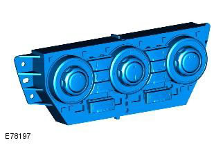
The ATC module is mounted in the center console and integrated into the control panel. The module works in combination with the ECM to control all aspects of the heating, ventilation, and air conditioning. An 18-pin electrical connector on the rear of the module provides a hardwired connection, a CAN bus connection, and a LIN bus connection to interface with A/C system components and other vehicle control modules. For additional information, refer to: Communication Network (418-00 Module Communication Network, Description and Operation).
Depending on the vehicle specification, there are six different ATC modules (two single-zone and four dual-zone). Low-spec vehicles have three rotary controls and three momentary switches with top-axis control to control air quality, temperature and distribution in the cabin. High-spec vehicles have three rotary controls, six momentary switches with top-axis control and two dual function switches to control air quality, temperature and distribution in the cabin.
In addition to the A/C system, the ATC module also controls the following functions:
- Heated seats
- Rear window heating
- Heated windshield
- Heated exterior rear view mirrors
For more information, please refer to the "How it works" section below.
Compressor solenoid valve
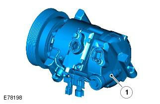
| Pos. | Spare part number | Name |
| 1 | - | Compressor solenoid valve. |
The compressor solenoid valve is integrated with the A/C compressor. The solenoid valve is controlled by the ECM using pulse width modulated (PWM) signals of varying levels. By controlling the flow of refrigerant through the compressor, the solenoid valve can control the operating temperature of the evaporator and the humidity in the cabin by changing the pressure in the A/C system.
NOTE: The A/C compressor solenoid valve is only installed on i6 gasoline vehicles.
For more information, refer to the chapter: Air Conditioning (412-01 Climate Control, Description and Operating Principle).
Refrigerant pressure sensor
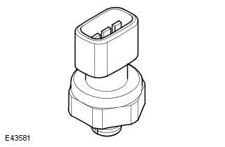
The refrigerant pressure sensor provides the ECM with a pressure input signal in the high-pressure side of the refrigerant system. The refrigerant pressure sensor is located in the refrigerant line between the condenser and the expansion valve.
The ECM supplies a 5-volt reference signal to the pressure sensor and receives a voltage return signal ranging from 0 to 5 volts, depending on the system pressure. The ECM uses the signal from the sensor to protect the refrigerant system from pressure spikes.
If the refrigerant system pressure exceeds the minimum or maximum pressure limit, the ECM will:
- disable A/C Compressor (TD4 vehicles)
- reduce A/C Compressor Flow (i6 vehicles)
If reducing the A/C compressor flow does not allow the system to return back to the optimum pressure range, the ECM in the i6 engine will turn off the A/C compressor.
The ECM continuously sends a refrigerant system pressure signal to the ATC module. The signal is transmitted from the ECM to the Central Junction Box (CJB) via the high-speed CAN bus. The CJB serves as a gateway and transmits the pressure signal to the ATC module via the medium-speed CAN bus.
If the refrigerant system pressure rises above the maximum pressure limit, the ATC module increases the amount of recirculated air entering the cabin. This helps lower the refrigerant system pressure and thus helps avoid the need to turn off the A/C compressor.
Evaporator temperature sensor
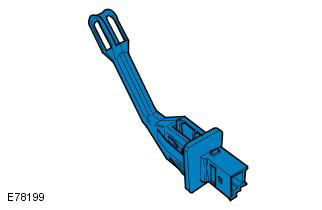
The evaporator temperature sensor is a negative temperature coefficient (NTC) thermistor. The sensor is mounted on the left side of the heater body and measures the temperature of the cooled air as it passes through the evaporator. The sensor receives a 5V reference supply voltage from the ATC module. By monitoring the return signal voltage, the ATC module can calculate the resistance of the sensor and therefore the evaporator temperature.
Interior temperature sensor
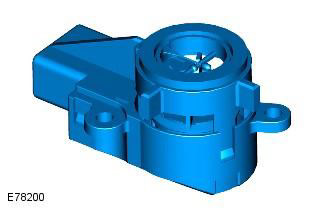
(Details can be found on the website www.LRman.ru)
The cabin temperature sensor is an NTC thermistor with an electric fan. The sensor is mounted behind the grille on the driver's side of the instrument panel near the steering column.
NOTE: The interior temperature sensor is only installed on vehicles with a dual-zone automatic climate control system.
The electric fan receives electrical power from the ATC module and draws air from the cabin through the grille above the thermistor. The thermistor receives a 5-volt reference supply voltage from the ATC module. By monitoring the return signal voltage, the ATC module can calculate the cabin air temperature.
Humidity sensor in the cabin
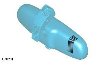
The interior humidity sensor is located inside the interior mirror and consists of three separate elements:
- Humidity sensor
- Air temperature sensor
- Windshield Temperature Sensor
NOTE: The interior humidity sensor is only available as an option.
The readings from these three sensors are combined to reduce the effect of moisture on the windshield.
The sensitive element of the humidity sensor is located under a nylon mesh cover. The sensor contains an element made of film capacitors on various bases. The dielectric separating the plates is made of a polymer that absorbs or evaporates moisture in proportion to the relative humidity of the air passing through the sensor. This causes a change in the capacitance of the sensor.
The humidity in the cabin is controlled by raising or lowering the evaporator temperature. Increasing the evaporator temperature increases the moisture content of the cabin air. Decreasing the evaporator temperature decreases the moisture content of the cabin air.
The sensor capacitance data, along with both temperature values, are transmitted as messages via the LIN bus to the ATC module. The ATC module uses these signals to calculate the dew point of the air on the windshield. When the windshield temperature reaches or drops below this value, moisture may appear on the glass. At this point, the ATC module will:
- raise the temperature of the air coming out of the heater
- adjust the position of the stepper motor for supplying air to the windshield (de-icing)
- adjust the position of the air intake stepper motor
- reduce A/C compressor flow (i6 vehicles only)
- supply power to the windshield heating elements (if equipped)
Outside air temperature sensor
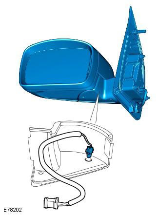
The outside air temperature sensor is an NTC thermistor. It is mounted in the left outside rearview mirror. The sensor receives a 5 V reference supply voltage from the ECM. By monitoring the return signal voltage, the ECM can calculate the resistance of the sensor and therefore the outside air temperature. The ECM transmits the outside air temperature value via the high speed CAN bus. This value is transmitted by the CJB to the ATC module via the medium speed CAN bus.
Solar radiation sensor
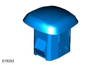
The solar radiation sensor is mounted in the centre of the upper surface of the instrument panel. The sensor contains a photocell which provides the CJB with an input signal of the intensity of sunlight, equivalent to the effect of solar radiation on the cabin heating.
The solar heating efficiency value is transmitted from the CJB to the ATC module via the medium speed CAN bus. The ATC module compensates for the effects of solar heating by adjusting the blower fan speed, air outlet temperature and air distribution, which helps maintain the desired cabin temperature.
Pollution sensor
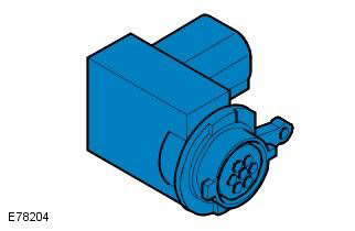
The pollution sensor allows the ATC module to monitor the outside air for the presence of hydrocarbon oxide (CO) and nitrogen oxides (NOx). The sensor is installed on the right side of the heater housing.
NOTE: The pollution sensor is installed as an option on vehicles with dual-zone automatic climate control.
The pollution sensor receives power from the battery junction box (BJB) when the ignition is on and sends one of the following four signals to the ATC module based on the outside air quality:
- Static or reduced pollution levels
- Slight increase in pollution levels
- Average increase in pollution levels
- A rapid or large increase in pollution levels
Based on the signal from the pollution sensor, the ATC module is able to control the intake air supply to reduce the penetration of pollutants into the cabin. This function operates fully automatically, but can be overridden by manually selecting the air supply source using the fresh/recirculated air switch on the control panel
Comments on this article