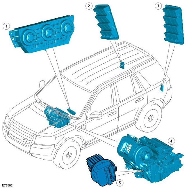
| Pos. | spare part no | Name |
| 1 | - | Temperature control module (ATC) |
| 2 | - | Right vent |
| 3 | - | Left vent |
| 4 | - | Heater assembly |
| 5 | - | Blower fan motor control module |
There are two options for the heating and ventilation system. Vehicles with a higher level of equipment are equipped with a dual-zone automatic system that allows you to set different temperature settings in the left and right side of the cabin. The dual zone system can also be equipped with a pollution sensor that monitors the quality of the air in the cabin.
Vehicles with a lower trim level use a manual single zone system.
In both systems, the heater assembly is installed along the axis of the vehicle, between the instrument panel and the partition of the engine compartment.
The ATC module controls the operation of the blower fan motor using the appropriate control module, which is installed on the bulkhead of the engine compartment on the side of the heater body assembly. For more information, see the chapter: (412-01 Climate control):
- Air distribution and purification (Description and principle of operation)
- Air conditioning (Description and principle of operation)
- Control Components (Description and principle of operation)
- Some vehicles are also equipped with an auxiliary heater. For more information, see the chapter: (412-02 Additional climate control).
- Auxiliary electric heater (Description and principle of operation)
- Auxiliary fuel heater (Description and principle of operation)
Automatic temperature control module
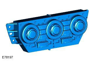
Air distribution and temperature controlled by automatic temperature control module (ATC), integrated with the control panel. On commands from the control panel, the ATC module controls the operation of the 3-step (in a single zone system) or 5 step (in a two-zone system) electric motor, which is installed on the heater body assembly. For more information, see the chapter: Control Components (412-01 Climate control, Description and principle of operation).
Heater assembly
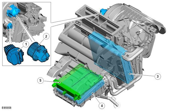
| Pos. | spare part no | Name |
| 1 | - | Blower fan motor control module |
| 2 | - | Electric blower fan |
| 3 | - | Air conditioning evaporator (A/C) |
| 4 | - | heater radiator |
| 5 | - | Electric auxiliary heater |
The heater assembly controls the temperature of the air supplied to the distribution ducts as directed by the ATC module. The heater assembly is installed along the axis of the vehicle and includes the following elements:
- Electric blower fan
- heater radiator
- Cabin air filter. For more information, see the chapter: Air distribution and purification (412-01 Climate control, Description and principle of operation).
- A/C evaporator. For more information, see the chapter: Air conditioning (412-01 Climate control, Description and principle of operation).
- Air intake damper and stepper motor. For more information, see the chapter: Control Components (412-01 Climate control, Description and principle of operation).
- Damper and stepper motors for air distribution. For more information, see the chapter: Control Components (412-01 Climate control, Description and principle of operation).
- Temperature mixing dampers and associated stepper motors. For more information, see the chapter: Control Components (412-01 Climate control, Description and principle of operation).
- Additional electric heater (in the presence of). For more information, see the chapter: Electric Booster Heater (412-02 Auxiliary Climate Control, Description and principle of operation).
Electric blower fan
The electric blower is a centrifugal fan driven by an electric motor. The operation of the electric fan is controlled by the ATC module together with the electric fan control module. The ATC module supplies the electric fan control module with pulse-width modulated (PWM) signal based on the set fan speed. The blower control module interprets the PWM signal as the speed of the blower and controls the voltage applied to the blower accordingly. For more information, see the chapter: Control Components (412-01 Climate control, Description and principle of operation).
Heater radiator
The heater core heats the air supplied to the passenger compartment. The heater radiator is an aluminum two-way finned tube heat exchanger installed across the heater. The heater radiator is connected to the engine cooling system by two aluminum tubes passing through the partition of the engine compartment. When the engine is running, the coolant pump constantly pumps coolant through the heater core. For more information, see the chapter:
- Engine cooling (303-03A Engine Cooling - 3.2L NA - I6, Description and function)
- Engine cooling (303-03B Engine Cooling - 2.2L Duratorq - Td4, Description and function)
Exhaust vents
Air vents allow free passage of air through the vehicle interior. The outlets are mounted on the left and right rear side panels of the body behind the rear lights.
The ventilation nozzles consist of a grid closed with a soft rubber damper, which acts as a non-return valve. The rubber damper automatically takes the desired position depending on the pressure difference in the passenger compartment and outside.
Comments on this article