Contents: Arrangement of elements ⇩ General information ⇩ Supply air duct ⇩ Air movement through the supply air…⇩ Fan ⇩ Heater ⇩ Air flow through the heater ⇩ Stepper motors ⇩ Diagnostics of stepper motors ⇩ Ventilation nozzles ⇩
Arrangement of elements
NOTE: RHD shown in picture (car with left-hand steering) shown, LHD (car with right-hand steering) has a similar device.
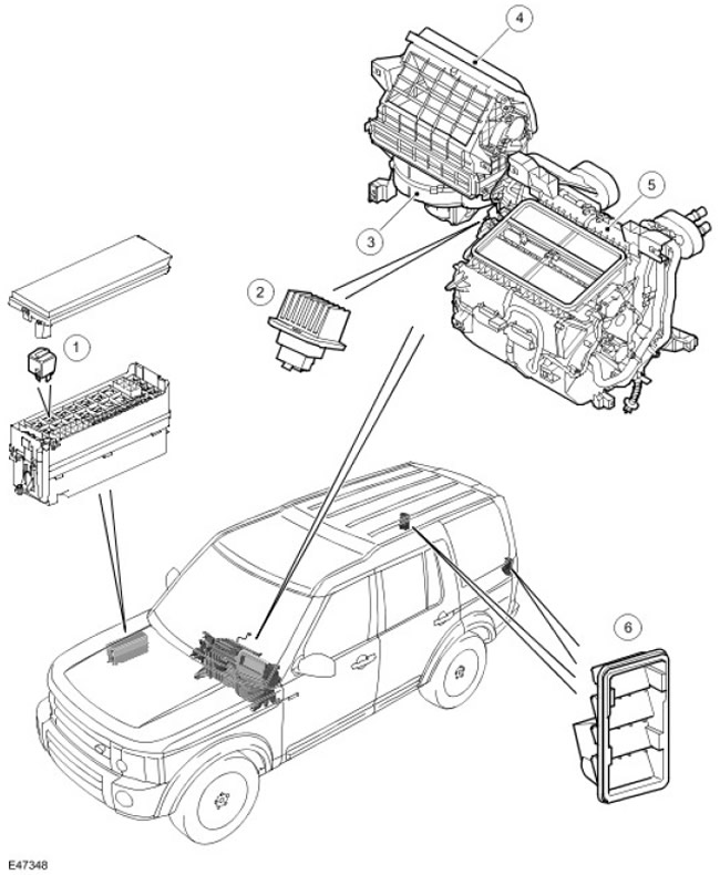
| Item name | Spare part catalog number | Description |
| 1 | - | Fan relay |
| 2 | - | Fan control module |
| 3 | - | Blowing fan |
| 4 | - | Supply air duct |
| 5 | - | Heater |
| 6 | - | Ventilation nozzles |
General information
The heating and ventilation system maintains the required temperature and air flow supplied to the vehicle interior. The system includes the following elements:
- Supply air duct.
- Fan.
- Fan control module.
- Fan relay.
- Heater.
- Two outlet ventilation pipes.
Supply air duct
NOTE: The picture shows a RHD vehicle (), the LHD vehicle () is mirror image.
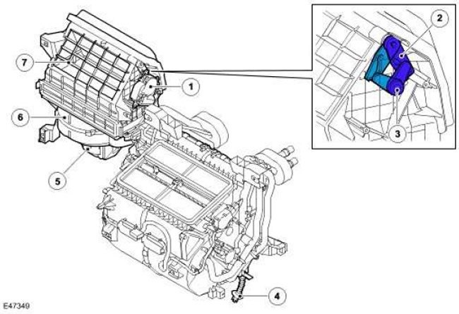
| Item name | Spare part catalog number | Description |
| 1 | - | Recirculation loop damper motor |
| 2 | - | Recirculation circuit flap lever |
| 3 | - | Electric recirculation circuit drive lever |
| 4 | - | Evaporator drain pipe |
| 5 | - | Blowing fan |
| 6 | - | Supply air duct |
| 7 | - | Recirculation loop inlet channel |
The fresh air duct is installed behind the control panel on the front passenger side and connects the mixing chamber, located under the windshield, and the heater.
The mixing chamber is formed by the upper and lower casings, as well as the molding. Fresh air enters the mixing chamber through the molding. From the mixing chamber, the air enters the moisture separator and then the inlet pipe of the supply air duct.
The supply air duct has a grille through which recirculated air from the passenger compartment enters the intake pipe. The supply air duct also contains the following components:
- Cabin Air Purifier Filter. For more information, see Air Distribution and Filtering (412-01 Air Distribution and Filtering)
- Fan.
- Fan control module.
To select the air source, a recirculation flap is installed between the fresh air intake and interior air intake pipes. The lever on the recirculation flap is driven by the flap's electric motor. The operation of the recirculation flap in automatic mode is controlled by the ATC controller. (automatic temperature control), and manually - by a switch on the ATC controller control panel (automatic temperature control). For more information, see Control Components (412-04 Control Components)
The original article can be found here lrman.ru
Fresh or recirculated air enters the supply air duct and, after passing through the air cleaning filter in the cabin, enters the fan inlet. From the fan, air enters the heater through the outlet of the supply air duct. Air movement in the supply air duct is ensured by the operation of the fan and the counter pressure when the car is moving.
Air movement through the supply air duct
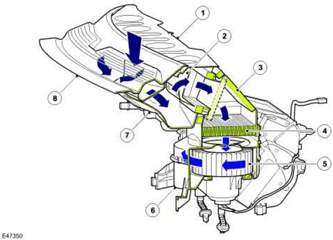
| Item name | Spare part catalog number | Description |
| 1 | - | Upper casing |
| 2 | - | Moisture separator |
| 3 | - | Recirculation loop damper |
| 4 | - | Cabin Air Purification Filter |
| 5 | - | Blowing fan |
| 6 | - | Supply air duct casing |
| 7 | - | Lower casing |
| 8 | - | Mixing chamber molding |
Fan
The fan is installed in the air intake duct under the cabin air filter. It is an open centrifugal fan driven by an electric motor. The fan is controlled by the ATC controller. (automatic temperature control) via the fan relay which is located in the BJB (distribution block of the battery), and a fan control module. The fan control module is installed in the fresh air duct behind the fan, the air flow of which removes the heat generated during module operation. The recirculation flap motor, fan and fan control module are connected by a wiring harness on the fresh air duct to the common wiring harness of the vehicle.
When the fan needs to operate, the ATC controller (automatic temperature control) supplies power to the fan relay coil. Once activated, the relay supplies power from the battery to the fan motor, which is connected to ground through the fan control module. The fan speed is controlled by the fan control module, which varies the supply voltage to the fan motor according to the PWM (pulse width modulated signal), received from the aTc controller (automatic temperature control). To change the supply voltage of the fan motor, the ATC controller (automatic temperature control) changes the duty cycle of the PWM signal (pulse width modulation).
In automatic fan mode, the ATC controller (automatic temperature control) changes the fan speed in accordance with the algorithm for maintaining comfortable conditions. In manual fan mode, the ATC controller (automatic temperature control) sets one of seven fixed fan speeds selected on the control panel. For more information, see Control Components (41204 Control Components)
Heater
NOTE: RHD model shown (), LHD model () has similar arrangement.
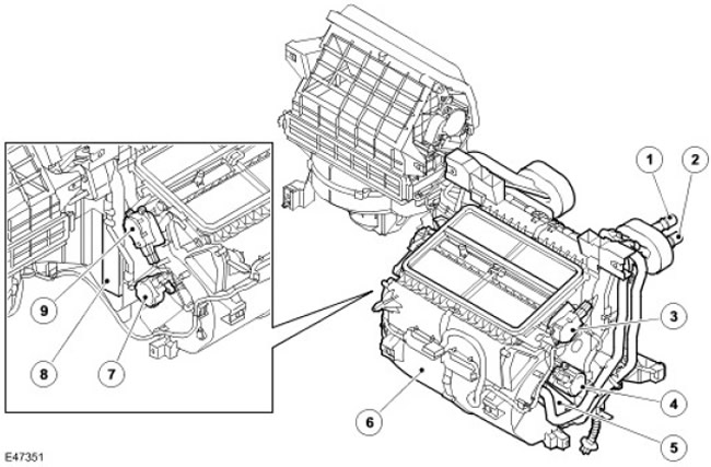
| Item name | Spare part catalog number | Description |
| 1 | - | Cooling system outlet pipe |
| 2 | - | Cooling system inlet pipe |
| 3 | - | Windshield defroster motor |
| 4 | - | RH (right) temperature control flap motor |
| 5 | - | Heater radiator |
| 6 | - | Heater casing |
| 7 | - | LH (left) temperature control flap motor (for automatic systems only) |
| 8 | Evaporator | |
| 9 | Air distribution flap motor for face and feet |
The heater regulates the temperature of the air supplied to the distribution ducts under the control of the ATC controller. (automatic temperature control). The heater is installed in the middle of the car, between the instrument panel and the engine compartment bulkhead. The heater consists of a molded plastic housing, which contains the evaporator, heater radiator and control flaps. Through internal channels built into the casing, air passes through the casing and is divided into two streams, one is directed to the LH () nozzle, and the second to the RH () nozzle.
When the A/C system is running (air conditioning), the evaporator cools the air entering the heater.
The heater core heats the air supplied to the air distribution ducts. The heater core is an aluminum two-pass heat exchanger made of finned tubes, installed across the heater housing. The heater core is connected to the engine cooling system by two aluminum tubes passing through the bulkhead of the engine compartment. When the engine is running, the coolant pump constantly pumps coolant through the heater core. If the vehicle is equipped with a fuel-driven coolant heater (FFBH), when the FFBH is turned on, the circulation of the coolant is enhanced by an electric circulation pump. For more information, refer to Auxiliary Heater (412-02B Auxiliary Heating)
Two temperature control flaps, LH () and RH (), regulate the air flow through the heater radiator, thereby maintaining the desired air temperature at the heater outlet. In automatic systems, both temperature control flaps operate independently, allowing different temperatures to be maintained on the LH () and RH () nozzles. In manual systems, the temperature control flaps are linked to each other and maintain the same temperature on the LH () and RH () nozzles.
Air flow through the heater
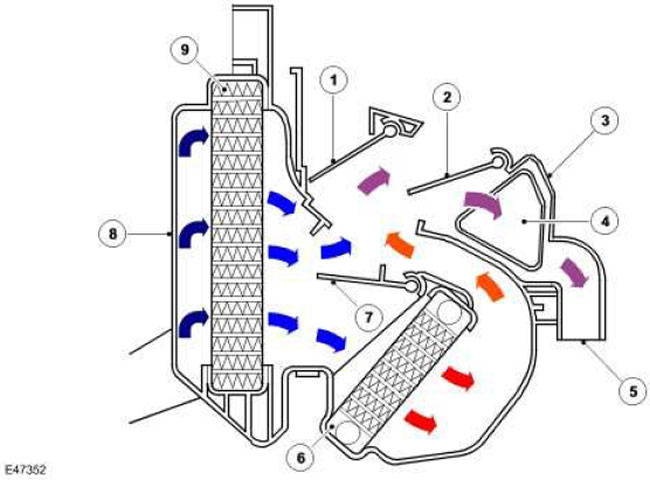
| Item name | Spare part catalog number | Description |
| 1 | - | Windshield defroster flap |
| 2 | - | Air distribution flap to the face and feet |
| 3 | - | Heater casing |
| 4 | - | Front air nozzle for supplying air to the legs |
| 5 | - | Rear footwell air vent |
| 6 | - | Heater radiator |
| 7 | - | Temperature regulator flap |
| 8 | - | Supply air duct casing |
| 9 | - | Evaporator |
Stepper motors
In automatic RH () and LH () systems, the temperature control flaps are driven by separate stepper motors. In manual RH () and LH () systems, the temperature control flaps are driven by a single stepper motor.
Stepper motors can also operate air distribution flaps. The first is operated by the windshield defroster motor, and the second by the face and foot air distribution motor.
When replacing a stepper motor, make sure the new component is identical to the old one. Although the stepper motors are externally identical, they are different in design. Therefore, installing the wrong motor can lead to failure.
The operation of the stepper motors of the air distribution flaps and the temperature control flaps is controlled by the ATC controller. (automatic temperature control), which is connected to stepper motors via a local LIN bus.
All stepper motors have microprocessors that store position information. To ensure proper control of stepper motors using the ATC controller (automatic temperature control), you must enter the following information for each engine:
- range of movement between extreme positions,
- the position of each engine relative to the boundaries of the established range.
Under normal conditions, the information stored in the memory of the stepper motors and the ATC controller (automatic temperature control), matches. In this case, the ATC controller (automatic temperature control) believes that there are no problems and the system is running normally. If discrepancies are detected, the ATC controller (automatic temperature control) performs the calibration procedure.
The stepper motor calibration procedure usually takes about 15 seconds, but in some cases it can take up to 2 minutes. During this procedure:
- LED (light-emitting diode) for programmable glass defrost function, located on the front panel of the ATC module (automatic temperature control), blinking.
- All other climate control system operations are suspended.
- Turn off the ignition.
- Turn the ignition back on.
- Check if the LED () of the programmable glass defrost function is flashing.
Automatic calibration: ATC controller (automatic temperature control) automatically initiates the calibration procedure every 175 hours of vehicle operation. It is performed for approximately 1 minute during the first ignition switch-off after the expiration of the next 175 hours. In this case, the LED () of the programmable glass defrost function does not flash.
Forced Calibration: ATC controller can be manually initiated (automatic temperature control) to perform an extraordinary calibration procedure for the stepper motors. To do this, turn on the ignition while holding down the ECON button and the recirculation button on the ATC controller panel (automatic temperature control). ATC controller (automatic temperature control) will perform the stepper motor calibration procedure, but instead of the LED () of the programmable glass defrost function, the LED () ECON will flash.
Diagnostics of stepper motors
The troubleshooting procedures for stepper motors in the heating system can be divided into two main groups:
- Electrical System Malfunctions DTC is generated (diagnostic trouble code) and is stored in the ATC controller memory (automatic temperature control).
- Mechanical System Malfunction The programmable defrost LED () will flash to alert the driver that the ATC controller (automatic temperature control) is attempting to perform a calibration procedure.
- replacing one or more stepper motors
- aTC controller replacement (automatic temperature control)
- a foreign object entering the system, causing the electric motor to jam
Ventilation nozzles
The air vents provide free air flow through the vehicle interior. The vents are mounted on the LH () and RH () rear side panels of the body behind the rear side lights.
The ventilation nozzles consist of a grille covered with a soft rubber flap, which functions as a check valve. The rubber flap automatically takes the required position depending on the difference in pressure in the cabin and outside.
Comments on this article