Contents: Arrangement of elements ⇩ General information ⇩ ATC module ⇩ System control panel in manual mode ⇩ Automatic system control panel ⇩ Input and output signals ⇩ Outside air temperature sensor ⇩ Refrigerant pressure sensor ⇩ Evaporator temperature sensor ⇩ Cabin air temperature sensor ⇩ Humidity sensor (if any) ⇩ Solar radiation sensor ⇩ Pollution sensor ⇩ A/C Compressor Control (air…⇩ A/C Compressor Shaft Torque (air…⇩ Idle mode control ⇩ Electrical load regulation ⇩ Engine warm-up time ⇩ Electrical load management during…⇩ Electrical load control when…⇩ Continuous electrical load management ⇩ Cooling system fan control ⇩ Air temperature regulators ⇩ Air distribution regulator ⇩ Fan control ⇩ Programmed glass defrosting ⇩ Air flow regulation ⇩ Determination of air pollution ⇩ Humidity measurement ⇩ Front seat heaters ⇩ Time until switching to low…⇩ Rear window defroster ⇩ Rear window heating phases ⇩ Windscreen heater ⇩ Windshield heater activation phases ⇩ Manual control system control diagram ⇩ Automatic system control diagram ⇩
Arrangement of elements
NOTE: Vehicle shown is RHD equipped. (left hand drive), car with LHD (right hand drive) has a similar device.
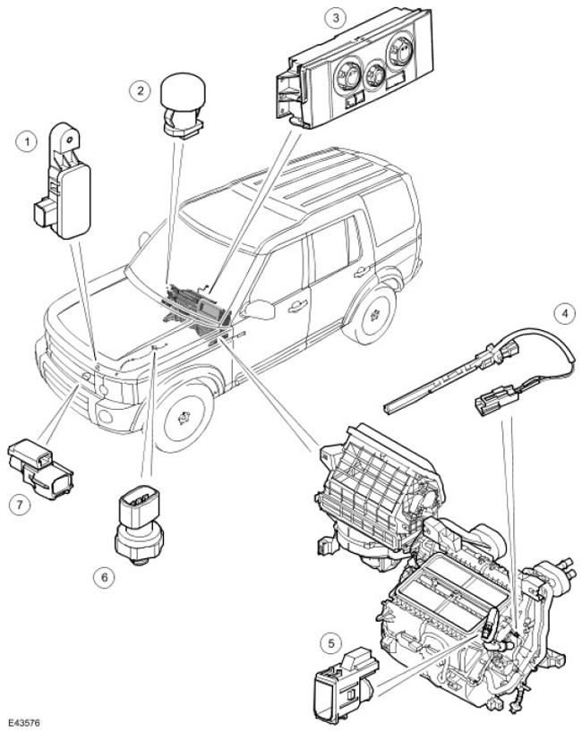
| Item name | Spare part catalog number | Description |
| 1 | - | Pollution sensor (for Japan only) |
| 2 | - | Solar radiation sensor |
| 3 | - | ATC controller (automatic temperature control) |
| 4 | - | Evaporator temperature sensor |
| 5 | - | Car interior temperature sensor, car interior temperature and humidity sensor (for Japan only) |
| 6 | - | Refrigerant pressure sensor |
| 7 | - | Outside air temperature sensor |
General information
The control system regulates the operation of the A/C system. (air conditioning), heating and ventilation, maintaining the set air temperature and its distribution in the cabin.
The vehicle may be equipped with a manual or automatic control system. The manual control system maintains a constant temperature at the heater outlet for the right and left sides of the passenger compartment, but allows manual selection of the air intake source, fan speed, and air distribution in the passenger compartment. The automatic system automatically regulates the temperature, volume, and distribution of air coming out of the heater, maintaining individual temperature modes set for the LH (left) and RH (right) sides of the passenger compartment. The automatic system also allows manual forced selection of the air intake source, fan speed, and air distribution. The manual and automatic systems include the following components.
- ATC controller (automatic temperature control).
- Outside air temperature sensor.
- Refrigerant pressure sensor.
- Evaporator temperature sensor.
- Interior air temperature sensor.
- Solar radiation sensor.
- Pollution sensor.
- Air humidity sensor.
ATC module
ATC controller (automatic temperature control) is installed in the center of the instrument panel. The integrated control panel contains push and rotary switches designed to control the LED system. (lEDs) on and near the switches light up to indicate the current system settings. In addition, when the headlights or parking lights are on, the switch symbols light up.
ATC controller (automatic temperature control) processes input signals from control panel switches, system sensors and the medium-speed CAN bus (local area network of controllers) and provides the proper control signals to the A/C system. (air conditioning), heating and ventilation. In addition to controlling the A/C system (air conditioning) aTC controller (automatic temperature control) also controls the following devices:
- Front Seat Heaters. For more information, contact Seats (501-10 Seating)
- Rear window defroster. For more information, see Glass, Frames and Mechanisms (501-11 Glass, Frames and Mechanisms)
- Windscreen Defroster. For more information, see Glass, Frames and Mechanisms (50111 Glass, Frames and Mechanisms)
- Windscreen Washer Nozzles and Outside Rear View Mirror Defrosters For more information, refer to Rear View Mirrors (501-09 Rear View Mirrors)
System control panel in manual mode
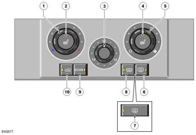
| Item name | Spare part catalog number | Description |
| 1 | - | Thermal relay |
| 2 | - | Front Seat Heating Switch LH (Left) |
| 3 | - | Air distribution switch |
| 4 | - | Front Seat Heating Switch RH (Right) |
| 5 | - | Fan switch |
| 6 | - | Rear Window Defogger Switch (models with heated windshields) |
| 7 | - | Rear Window Defogger Switch (models without heated windshields) |
| 8 | - | Windscreen Defogger Switch (if installed) |
| 9 | - | Economy mode switch |
| 10 | - | Air recirculation mode switch |
Automatic system control panel
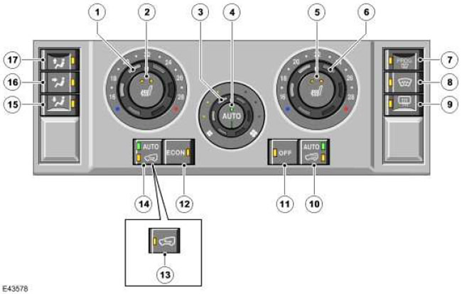
| Item name | Spare part catalog number | Description |
| 1 | - | Temperature switch in the LH (left) part of the cabin. |
| 2 | - | Front Seat Heating Switch LH (Left) |
| 3 | - | Fan switch |
| 4 | - | Automatic mode switch |
| 5 | - | Front Seat Heating Switch RH (Right) |
| 6 | - | Temperature switch in the RH (right) part of the cabin. |
| 7 | - | Switch for programmable glass defrost function |
| 8 | - | Windscreen heating switch |
| 9 | - | Rear Window Defogger Switch |
| 10 | - | Additional climate control system switch |
| 11 | - | System switch |
| 12 | - | Economy mode switch |
| 13 | - | Switch for recirculation of air in the cabin (models without pollution sensor) |
| 14 | - | Switch for recirculation of air in the cabin (models with pollution sensor) |
| 15 | - | Air distribution switch: at foot level |
| 16 | - | Air distribution switch: at face level |
| 17 | - | Air distribution switch: windshield |
Input and output signals
Communication between ATC controller (automatic temperature control) and on-board electrical wiring is carried out through four electrical connectors. Signals from the control system sensors are sent via wired communication to the ATC controller input (automatic temperature control). In addition, the ATC controller (automatic temperature control) uses the local LI N bus to exchange data with the additional climate control system, the damper drive motors in the heater module and the medium-speed CAN bus (local area network controller) to communicate with other onboard control modules. For more information, refer to the Communications Network (418-00 Module Communications Network)
Outside air temperature sensor
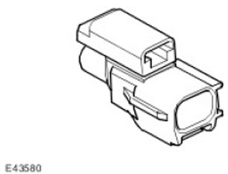
The outside air temperature sensor is an NTC thermistor. (negative temperature coefficient), which is fed to the ATC controller input (automatic temperature control) outside air temperature signal. The sensor is mounted on a bracket located at the rear in the center of the bumper beam.
Refrigerant pressure sensor
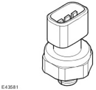
The refrigerant pressure sensor supplies the ATC controller input (automatic temperature control) pressure signal in the high-pressure line of the refrigerant circuit. The refrigerant pressure sensor is located in the refrigerant line between the condenser and the thermostatic expansion valve.
ATC controller (automatic temperature control) supplies a 5V reference voltage to the refrigerant pressure sensor and receives a return voltage signal in the range between 0 and 5V corresponding to the system pressure.
ATC controller (automatic temperature control) uses the pressure signal from the refrigerant pressure sensor to protect the system from overpressurization and to calculate the A/C system compressor load (air conditioning) on the engine. ATC controller (automatic temperature control) also transmits load data from the A/C system compressor (air conditioning) to the ECM module (engine control module) via medium-speed CAN bus (local area network controller), as well as to the instrument panel and via the high-speed CAN bus (local area network controller). This information is used to control the speed of the engine cooling fan.
To protect the system from excessive pressure, the ATC controller (automatic temperature control) sets for A/C system compressor (air conditioning) minimum possible flow rate if pressure:
- decreases to 1.9±0.2 bar (27.5±3 psi), ATC controller (automatic temperature control) restores load on the A/C system compressor (air conditioning), when the pressure rises to 2.8±0.2 bar (40.5±3 psi).
- increases to 33±1 bar (479±14.5 psi), ATC controller (automatic temperature control) restores load on the A/C system compressor (air conditioning), when the pressure decreases to 23.5±1 bar (341±14.5 psi).
Evaporator temperature sensor
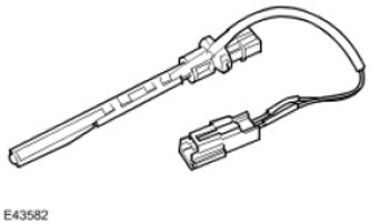
The evaporator temperature sensor is an NTC thermistor (negative temperature coefficient), transmitting to the ATC controller (automatic temperature control) evaporator outlet temperature signal. The evaporator temperature sensor is installed on the right side of the heater casing.
ATC controller (automatic temperature control) based on the evaporator temperature sensor readings, it sets the load on the A/C system compressor (air conditioning) and thus regulates the operating temperature in the evaporator.
Cabin air temperature sensor
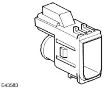
The cabin air temperature sensor is an NTC thermistor (negative temperature coefficient), mounted behind the grille of the center console trim on the driver's side. The sensor is connected to a tube, the other end of which is connected to a diffuser located on the side of the heater unit housing. Air coming from the heater and passing through the diffuser causes air to move through the tube, which leads to air being drawn through the grille from the passenger compartment, which passes through the temperature sensor.
Humidity sensor (if any)
The capacitive humidity sensor is built into the cabin air temperature sensor (see above).
The sensitive element of the humidity sensor is a film capacitor on substrates made of various materials. The dielectric separating the plates is made of a polymer that absorbs or evaporates moisture proportionally to the relative humidity of the air passing through the sensor, and the sensor capacitance changes. To protect against mechanical impacts, the sensitive element is covered with a nylon mesh.
The humidity and temperature sensors in the cabin are connected to a printed circuit board located in the sensor housing. The printed circuit board is supplied with 5 V supply voltage from the ATC controller. (automatic temperature control)From the printed circuit board, separate temperature and humidity signals are sent to the ATC controller. (automatic temperature control).
Solar radiation sensor
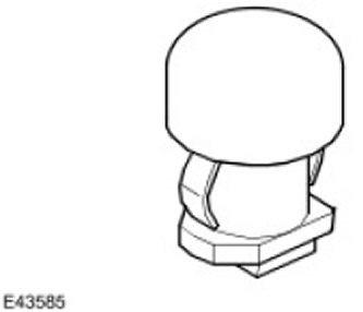
The solar radiation sensor consists of two photocells that feed into the ATC controller input. (automatic temperature control) light intensity signals, the first signal corresponds to the illumination on the left side of the car, and the second - on the right side. The signals are a measure of the intensity of heating of the car interior by the sun and are used by the ATC controller (automatic temperature control) to regulate fan performance, temperature and air distribution to improve comfort. The sensor is installed in the central part of the front panel, on top. It is supplied with 5 V supply voltage from the ATC controller (automatic temperature control).
Pollution sensor
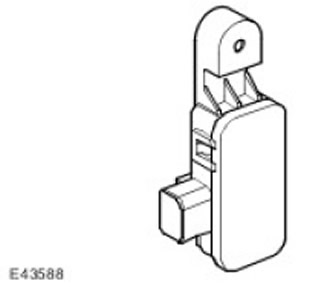
With the help of the pollution sensor the ATC controller (automatic temperature control) controls the level of gaseous hydrocarbons and oxides (nitrous oxide, sulfur oxides and carbon monoxide). The sensor is attached to a bracket, which is installed in the front part of the supporting element at the upper left corner of the capacitor.
The pollution sensor is supplied with power voltage from the battery via the ATC controller. (automatic temperature control). The sensor sends separate signals about the content of gaseous hydrocarbons and oxides.
In case of failure of the pollution sensor, the ATC controller (automatic temperature control) turns off the automatic operation of the recirculation circuit damper.
A/C Compressor Control (air conditioning)
A/C system compressor (air conditioning) is a permanently installed unit with variable capacity, driven by a motor. Refrigerant flow through the A/C compressor (air conditioning), as well as the resulting pressure in the system and the operating temperature of the evaporator are regulated by a solenoid valve in the refrigerant circuit. The operation of the solenoid valve in the refrigerant circuit is controlled by the ATC controller (automatic temperature control) using PWM signal (pulse width modulation), modulated at a frequency of 400 Hz. The duty cycle of the signal PwM (pulse width modulation) is calculated using the following parameters:
- A/C Compressor Shaft Torque (air conditioning).
- Maximum torque on the A/C compressor shaft (air conditioning)
- A/C Cooling System Status (air conditioning).
- A/C system load (air conditioning).
- A/C system refrigerant pressure (air conditioning).
- Outside air temperature
- Fan speed
- Crankshaft scrolling condition
- Evaporator temperature.
- Current gear of the gearbox.
If the economy mode is selected, the PWM signal (pulse width modulation) holds the solenoid valve in the refrigerant circuit in the position corresponding to the minimum permissible flow, thereby effectively turning off the A/C function (air conditioning).
ATC controller (automatic temperature control) sets the operating pressure limits of the refrigerant system. When the system pressure approaches the upper limit, the duty cycle of the PWM signal (pulse width modulation) gradually decreases until the system pressure begins to decrease. If the system pressure drops below the lower limit, the duty cycle of the PWM signal (pulse width modulation) maintained at a minimum level to ensure minimum A/C compressor piston stroke (air conditioning), at which the amount of oil in the A/C system compressor (air conditioning) does not decrease. The protective algorithm allows you to quickly and at an early stage detect a sharp change in pressure associated with a malfunction in the system.
A/C Compressor Shaft Torque (air conditioning)
ATC controller (automatic temperature control) calculates the torque on the A/C compressor shaft based on refrigerant pressure, evaporator temperature and engine speed (air conditioning). The calculated value is transmitted via the medium-speed CAN bus. (local area network controller) to the ECM module (engine control module), which uses this value to regulate the idle speed and the composition of the working mixture. In addition, the ATC controller (automatic temperature control) compares the calculated value with the maximum torque on the A/C system compressor shaft (air conditioning), received from the ECM module (engine control module) via medium-speed CAN bus (local area network controller). If the calculated value exceeds the maximum value, the ATC controller (automatic temperature control) commands the solenoid valve in the refrigerant circuit to reduce the flow of refrigerant in order to reduce the torque on the A/C compressor shaft (air conditioning). By reducing the maximum torque on the A/C compressor shaft (air conditioning), ECM module (engine control module) can, if necessary, reduce the load on the engine in order to maintain the traction characteristics of the vehicle or prevent damage to the cooling system.
Idle mode control
To ensure the operation of the A/C system (air conditioning), ATC controller (automatic temperature control) sends a request to increase the engine idle speed if the evaporator temperature has started to rise and the solenoid valve in the refrigerant circuit is already open, maintaining its maximum flow. The request message to increase the engine idle speed is sent in three stages via the medium-speed CAN bus (local area network controller) to the ECM module (engine control module). For more information, please contact Electronic Engine Controls (303-14A Electronic Engine Controls - 4.0L). For more information, please contact Electronic Engine Controls (303-14B Electronic Engine Controls - 4.4L). For more information, please contact Electronic Engine Controls (303-14C Electronic Engine Controls - 2.7L Diesel).
The reasons for changing the engine crankshaft speed in idle mode are defined as follows:
- If the evaporator temperature rises by 3° or exceeds the set operating temperature by 6° within 10 seconds, the first request to increase the engine idle speed is sent.
- If, after meeting the requirements of the first request to increase the engine's idle speed, the evaporator temperature rises by 3° or exceeds the set operating temperature by 12° within 9 seconds, a second request is sent to increase the engine's idle speed.
- If, after completing the requirements of the second request to increase the engine's idle speed, the evaporator temperature rises by 3° within 10 seconds or exceeds the set operating temperature by 15°, a third request to increase the engine's idle speed is sent.
- If, after the requirements of the third request to increase the engine idle speed are met, the evaporator temperature drops by 3° within 10 seconds, a request to decrease the engine idle speed is sent.
Electrical load regulation
ATC controller (automatic temperature control) regulates the load of the on-board electrical system for the following purposes:
- Maintain sufficient charge of the vehicle battery.
- Provide adequate power to heat and defrost windows while the engine is warming up.
- Provide proper power to the A/C system (air conditioning) during extended periods when the engine is idling.
- Maintain system voltage within acceptable limits.
- Provide adequate power according to customers' requirements.
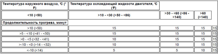
During engine warm-up, the ATC controller (automatic temperature control) controls the electrical load, ensuring that the battery voltage exceeds a preset level. This level, as well as the duration of the engine cranking, depend on the outside air and coolant temperature. After the engine has warmed up, the ATC controller (automatic temperature control) controls the electrical load, ensuring that the required electrical load does not exceed the generator capacity.
The duration of the engine warm-up period depends on the outside air and coolant temperature at the time the ignition is turned on. (see table below):
Engine warm-up time
ATC controller (automatic temperature control) calculates the electrical load from devices connected to the battery and generator, and compares the result with the maximum permissible load on the generator. The calculations determine the average value for the first 20 seconds after starting the engine, and then the average values for every subsequent 60 seconds. After the ignition is turned off, the ATC controller (automatic temperature control) maintains the electrical load readings for 20 seconds. If the engine is restarted within 20 seconds, the ATC (automatic temperature control) module resumes electrical load management using the stored status. If the engine is restarted after 20 seconds, the timers are reset and the ATC controller (automatic temperature control) recalculates the state.
If the electrical load exceeds the maximum allowable value, the ATC controller (automatic temperature control) sends a request message to increase the engine idle speed via the medium-speed CAN bus (local area network controller) on the eCm module (engine control module). If the electrical load exceeding the permissible limit remains even after the engine speed is increased in idle mode, or if the electrical load exceeds the capacity of the charging system, the ATC controller (automatic temperature control) reduces the electrical load by reducing or disabling the power consumption of some on-board systems. The number of systems controlled in this way depends on how much the load needs to be reduced. These systems, and the order in which they are reduced or disabled, are listed in three tables. The use of a particular table depends on the outside air temperature, battery temperature, and engine coolant temperature.
- The first table is used when starting the engine from a cold state at an air temperature of less than 5°C and a coolant temperature of less than 30°C.
- The second table is used when starting a warm engine at an air temperature of 5°C and above and a coolant temperature of less than 30°C.
- The third table is used when the battery temperature is 5°C or higher and the coolant temperature is more than 50°C.
- If none of the above conditions are met, the ATC controller (automatic temperature control) selects the table that was last used.
Electrical load management during cold start
| Priority | System | |
| Reducing energy consumption | Disconnection | |
| 1 | - | Air suspension |
| 2 | - | Front seat heaters |
| 3 | - | Infotainment system |
| - | 4 | Front seat heaters |
| 5 | - | Additional climate control fan |
| 6 | - | Rear window defroster |
| 7 | - | Heaters for outside rear view mirrors and windshield washer nozzles |
| - | 8 | Heaters for outside rear view mirrors and windshield washer nozzles |
| 9 | - | Windscreen heater |
| 10 | - | Main climate control fan |
| - | 11 | Additional climate control fan |
| - | 12 | Rear window defroster |
| - | 13 | Windscreen heater |
Electrical load control when starting a warm engine
| Priority | System | |
| Reducing energy consumption | Disconnection | |
| - | 1 | Heated front seats, outside rearview mirrors and windshield washer nozzles |
| 2 | - | Windscreen heater |
| 3 | - | Rear window defroster |
| 4 | - | Air suspension |
| 5 | - | Infotainment system |
| - | 6 | Windscreen heater |
| - | 7 | Rear window defroster |
| 8 | - | Additional climate control fan |
| - | 9 | Additional climate control fan |
Continuous electrical load management
| Priority | System | |
| Reducing energy consumption | Disconnection | |
| - | 1 | Front seat heaters |
| 2 | - | Windscreen heater |
| 3 | - | Rear window defroster |
| 4 | - | Additional climate control fan |
| 5 | - | Air suspension |
| 6 | - | Infotainment system |
| - | 7 | Additional climate control fan |
Changes in engine idle speed and changes in electrical load of systems not directly controlled by the ATC controller (automatic temperature control) (air suspension and infotainment system) is carried out using messages transmitted via the medium-speed CAN bus (local area network controller). If partial restriction of energy consumption is required
- The system continues to regulate the height of the air suspension, but the compressor performance is limited because the receiver is not filled.
- The infotainment system continues to operate, but the maximum volume level is reduced and the frequency range of the output signal is reduced.
Cooling system fan control
ATC controller (automatic temperature control) determines the required energy consumption for cooling in the condenser based on the refrigerant pressure (there is a direct relationship between the temperature and pressure of the refrigerant). The required cooling energy consumption is reported to the ECM. (engine control module) via medium-speed CAN bus (local area network controller). ECM module (engine control module) regulates condenser cooling using the cooling system fan. For more information, refer to Electronic Engine Controls (303-14A Electronic Engine Controls - 4.0L). For more information, please contact Electronic Engine Controls (303-14B Electronic Engine Controls - 4.4L). For more information, please contact Electronic Engine Controls (303-14C Electronic Engine Controls - 2.7L Diesel).
Air temperature regulators
From the evaporator, air enters the heater, where the temperature control flaps direct some of the air through the heater core to obtain the desired air temperature at the outlet. In models with automatic systems, both temperature control flaps operate independently, allowing different temperatures to be maintained on the left and right sides. In models with manual control, the temperature control flaps are driven by one stepper motor, and in automatic systems - by two. The ATC controller controls one or two stepper motors. (automatic temperature control) using messages transmitted via the local LI N bus.
ATC controller (automatic temperature control) calculates the stepper motor position required to reach the set temperature and compares it with the current stored position. If these positions do not match, the ATC controller (automatic temperature control) sends a command to the stepper motor to change position.
If the maximum cooling or maximum heating mode is selected, the ATC controller (automatic temperature control) cancels all previously set settings and sets the temperature, air source, fan speed and air distribution as shown in the following table.
NOTE: * If the engine is cold, a lockout may be activated which will stop the fan from operating until the engine warms up to operating temperature.
| Purpose | Maximum cooling | Maximum heating |
| Temperature control | The temperature control valve is completely closed. | The temperature control valve is fully open. |
| Air source | Recirculated air | Fresh air |
| Fan speed | Maximum | Maximum * |
| Air distribution | Air supply nozzle at face level (with air supply function to the legs) | Air nozzle for footwell and windshield |
In models with automatic systems, setting the system to maximum heating or cooling in one zone may affect the temperature regulation in the second zone. In practice, maximum cooling or maximum heating can only be achieved if the temperature controls for the two interior zones are set to the same extreme positions.
In economy mode, the automatic temperature control function continues to operate, but without cooling, the minimum outlet air temperature cannot be lower than the outside air temperature, and in practice it is even slightly higher due to heating in the intake air duct.
Air distribution regulator
When the A/C system (air conditioning) works in automatic mode, ATC controller (automatic temperature control) automatically regulates air distribution in accordance with the embedded algorithm for creating comfortable conditions. Automatic control is cancelled when manual modes are selected. Manual control of air distribution remains until automatic mode is selected again. The temperature regulator flaps are driven by two stepper motors controlled by the ATC controller (automatic temperature control), transmitting messages via the local LIN bus.
If the air distribution mode is selected with air supplied at both face and foot level, when the air is heated, most of it is directed to the feet. When the air is cooled, most of it is discharged at face level.
Fan control
If the A/C system is on (air conditioning) or manually set fan speed, ATC controller (automatic temperature control) supplies voltage to the fan coil in the BJB unit (battery distribution block). The activated relay supplies battery power to the fan motor, which is connected to ground via the fan control module. The fan speed is controlled by a PWM signal. (pulse width modulation), which is supplied from the ATC controller (automatic temperature control) to the fan control module. The fan control module regulates the voltage to the fan motor according to the PWM signal. (pulse width modulation).
In automatic fan mode, the ATC controller (automatic temperature control) changes the fan speed in accordance with the algorithm for maintaining comfortable conditions. In manual fan mode, the ATC controller (automatic temperature control) sets one of seven fixed fan speeds selected on the control panel.
Programmed glass defrosting
The programmed defrost function of the vehicle's windows automatically allows this procedure to be performed with the greatest efficiency. When the programmed defrost function of the windows is selected, the ATC controller (automatic temperature control) sets the following system configuration:
- Automatic operation mode is switched off.
- Outside air is supplied to the cabin, manual control.
- The previously selected temperature does not change, automatic control.
- Air is directed to the windshield, manual control.
- The fifth fan speed is set, manual control
- Rear and windshield heaters (if applicable) glass included.
- A/C system (air conditioning) is switched to automatic operation mode.
- Any air distribution switch is pressed. The system will react in the same way as a normal change of air distribution with manual control.
- Pressing the automatic mode switch. This press restores the fully automatic mode.
- Pressing the programmable defrost switch again. This press returns the system to the state that existed immediately before the programmable defrost function was first selected.
- Turn off the ignition.
Air flow regulation
The system automatically selects the air intake source unless this mode is cancelled by manually switching on recirculation. In automatic control mode, the ATC controller (automatic temperature control) determines the required position of the recirculation circuit damper in accordance with the algorithm for maintaining comfortable conditions and the input signal from the pollution sensor (if installed). The recirculation loop damper is driven by an electric motor, which is controlled by analog signals received via wire communication from the ATC controller. (automatic temperature control). The electric motor has a potentiometer that returns to the ATC controller. (automatic temperature control) position signal, providing automatic feedback control.
If recirculation is not selected as the air intake source, the ATC controller (automatic temperature control) regulates the position of the recirculation circuit flap, reducing the air flow from the counter-pressure when the vehicle is moving.
After the ignition is turned off, the ATC controller (automatic temperature control) measures the outside air temperature. If the outside air temperature is below the preset value, the recirculation mode is activated to prevent humid air from entering the passenger compartment while the vehicle is parked.
If the vehicle is in transport mode, each time the ignition is turned off, the ATC controller (automatic temperature control) sets the damper on the air intake line to the recirculation position regardless of the outside air temperature.
Determination of air pollution
If the vehicle is equipped with a pollution sensor, the ATC controller (automatic temperature control) selects the air intake source in such a way as to reduce the content of external pollutants in the incoming air. This function works completely automatically, but can be overridden by manually selecting the air supply source.
Humidity measurement
If a humidity sensor is installed, the ATC controller (automatic temperature control) regulates the humidity of the air in the car. Increasing the humidity of the air entering the car is achieved by increasing the temperature of the evaporator, and decreasing the humidity is achieved by decreasing the temperature of the evaporator.
Front seat heaters
To turn on the front seat heaters, turn the ignition switch to position II and select one of the two possible heating modes. When you first press the front seat heater switch, the ATC controller (automatic temperature control) sets the heating temperature to high, supplies power to the corresponding heating elements of the front seats. Two yellow LEDs on the switch light up (lEDs). When you press the switch a second time, the ATC controller (automatic temperature control) sets a low heating temperature, and one of the LEDs (lEDs) goes out. When the switch is pressed for the third time, the ATC controller (automatic temperature control) turns off the heating, and the second LED goes out (lEDs). The seat heaters remain on until they are turned off with the switch or until the ignition is turned off.
To the ATC controller input (automatic temperature control) receives signals from the temperature sensors of both front seats, based on which it regulates the power supply to the heating elements, controlling the temperature of the seats in the range between 35 and 45°C. The actual temperature settings depend on the type of seat upholstery, since the different materials used have different thermal conductivities.
If the front seat heaters are turned on in the high temperature mode, after a certain time the ATC controller (automatic temperature control) automatically switches them to low temperature mode. The time before switching depends on the air temperature in the cabin.
Time until switching to low temperature mode
| Cabin temperature,°C (°F) | <-15 (5) | -15-10 | -10-0 | 0 -15 | 15-25 | >25 (77) |
| Delay, minutes | Remains in high temperature mode until manually switched over | 20 | 15 | 10 | 5 | 3 |
To protect the heating elements, the ATC controller (automatic temperature control) turns off the front seat heating if the battery voltage exceeds 16.5±0.3 V for 5 seconds or more. After the battery voltage drops to 16.2±0.3 V, the front seat heating turns on again.
ATC controller (automatic temperature control) regulates the power supply to the heating elements and, if a short circuit or open circuit is detected, turns off the heating of the corresponding front seat. In addition, the ATC controller (automatic temperature control) turns off seat heating when the seat temperature exceeds the set value significantly.
Also ATC controller (automatic temperature control) monitors the reliability of signals coming from temperature sensors. If, with the seat heating on, the signal from one of the temperature sensors shows that the actual temperature is no more than 5°C (9°F) below the set value, the ATC controller (automatic temperature control) monitors the temperature rise from this sensor and checks that the temperature does not exceed the maximum or minimum allowable value. If the sensor temperature approaches the upper limit of the operating range under conditions where the outside air temperature and engine temperature coincide within 10°C (18°F), the ATC controller (automatic temperature control) turns off the front seat heating until the signal from the sensor indicates a drop in temperature to the preset value. ATC controller (automatic temperature control) interprets a signal from the temperature sensor corresponding to a temperature of -45°C or lower as an open circuit, and a signal corresponding to a temperature of 100°C or higher as a short circuit.
Rear window defroster
ATC controller (automatic temperature control) controls the operation of the rear window heater, sending it via the medium-speed CAN bus (local area network controller) messages that control the rear window defroster relay, which is located in the CJB (central distribution block). CJB control module (central switching unit) interprets messages received via the CAN bus (local area network controller), and switches the connections to the "ground" of the winding of the relay that controls the operation of the rear window heater. After activation of the rear window heater relay, power from the battery is supplied to the rear window heating elements. The rear window is heated only when the engine is running.
ATC controller (automatic temperature control) turns on the rear window defroster in certain cycles, changing the power and duration of heating. The characteristics of the heating cycle depend on the outside air temperature and whether this is the first or subsequent heating activation in the current ignition cycle.
When the heater switch is pressed, the ATC controller (automatic temperature control) activates the corresponding heating cycle, and the LED on the switch lights up (lEDs). The LED () will remain lit until the rear window defroster is turned off, the defroster cycle is completed, or the engine is stopped. If the engine is restarted within 20 seconds after the engine is stopped or the ignition is turned off, the rear window defroster will resume.
After the rear window defroster is turned on for the first time, the ATC controller (automatic temperature control) sets a short or long time interval with maximum defrost power, after which it switches to the reduced power mode. The defrost mode used depends on the outside air temperature. In the reduced power phase, the relay switches off the rear window heater after 80 seconds of operation and switches it on again after 40 seconds.
On subsequent starts in the current ignition cycle, the ATC controller (automatic temperature control) turns on the rear window heater at maximum power for a fixed period of time.
Rear window heating phases
| Phase | Time, minutes |
| Short defrost cycle (-5°C and above) | 10 |
| Long defrost cycle (below -5°C) | 15 |
| Reduced power | 20 |
| Subsequent heater activations | 10 |
Windscreen heater
ATC controller (automatic temperature control) controls the operation of the windshield heater using the windshield heater relay installed in the BJB unit (battery junction box). For this purpose, the ATC controller (automatic temperature control) switches the ground connections of the relay winding that controls the windshield heater. After the relay is switched on, power from the battery begins to flow to the two heating elements of the windshield heater. The windshield is heated only when the engine is running.
ATC controller (automatic temperature control) turns on the windshield heater in certain cycles, changing the power and duration of heating. The characteristics of the heating cycle depend on the outside air temperature and whether this is the first or subsequent heating activation in the current ignition cycle.
When the windshield defroster switch is pressed, the ATC controller (automatic temperature control) activates the corresponding heating cycle, and the LED on the switch lights up (lEDs). The LED () will remain lit until the windshield heater is turned off, the heating cycle is completed, or the engine is stopped. If the engine is restarted within 20 seconds after the engine is stopped or the ignition is turned off, the windshield heater will resume.
After the first time the windshield heater is turned on, the ATC controller (automatic temperature control) sets a short or long time interval with maximum heating power, after which it switches to the reduced power mode. The defrost mode used depends on the outside air temperature. In the reduced power phase, the relay switches off the windshield heater after 80 seconds of operation and switches it on again after 40 seconds.
On subsequent starts in the current ignition cycle, the ATC controller (automatic temperature control) turns on the windshield heater at maximum power for a fixed period of time.
Windshield heater activation phases
| Phase | Time, minutes |
| Short defrost cycle (-5°C and above) | 3 |
| Long defrost cycle (below -5°C) | 5 |
| Reduced power | 10 |
| Subsequent heater activations | 3 |
Manual control system control diagram
NOTE: A = Wired connections; D = High Speed CAN Bus (local area network controller); N = medium speed CAN bus (local area network controller); O = LIN bus
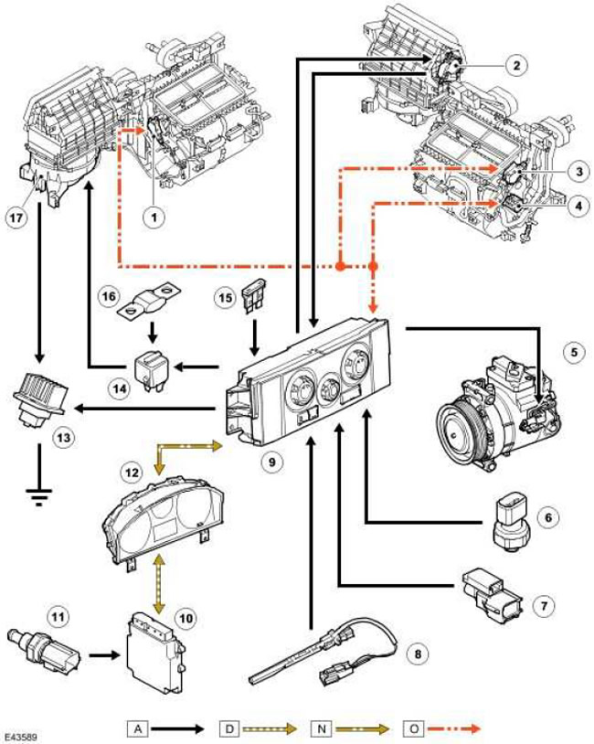
| Item name | Spare part catalog number | Description |
| 1 | Air distribution flap motor for face and feet | |
| 2 | Recirculation loop damper motor | |
| 3 | Windshield defroster motor | |
| 4 | Temperature regulator flap motor | |
| 5 | A/C Compressor Solenoid Valve (air conditioning) | |
| 6 | Refrigerant pressure sensor | |
| 7 | Outside air temperature sensor | |
| 8 | Evaporator temperature sensor | |
| 9 | ATC module (automatic temperature control) | |
| 10 | ECM (engine control module) | |
| 11 | ECT sensor (engine coolant temperature) | |
| 12 | Instrument panel. | |
| 13 | Fan control module | |
| 14 | Fan Motor Relay | |
| 15 | Fuse 51P, in CJB block (central switching unit) (constant power supply from the battery) | |
| 16 | Fuse link 12E, in BJB block (battery junction box) | |
| 17 | Blowing fan |
Automatic system control diagram
NOTE: A = Wired connections; D = High Speed CAN Bus (local area network controller); N = medium speed CAN bus (local area network controller); O = LIN bus
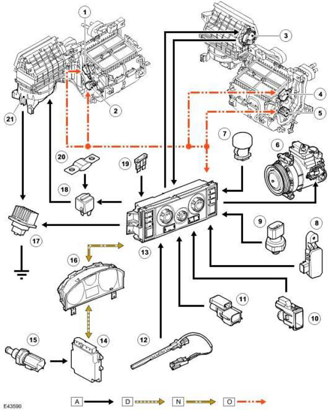
| Item name | Spare part catalog number | Description |
| 1 | Electric motor for air distribution flap to face and feet | |
| 2 | LH (left) temperature control flap motor | |
| 3 | Recirculation flap motor | |
| 4 | Windshield defroster motor | |
| 5 | RH (right) temperature control flap motor | |
| 6 | A/C Compressor Solenoid Valve (air conditioning) | |
| 7 | Solar radiation sensor | |
| 8 | Pollution sensor (for Japan only) | |
| 9 | Refrigerant pressure sensor | |
| 10 | Cabin air temperature sensor (all models with automatic system except those intended for Japan); cabin temperature and humidity sensor (automatic models for Japan only) | |
| 11 | Outside air temperature sensor | |
| 12 | Evaporator temperature sensor | |
| 13 | ATC module (automatic temperature control) | |
| 14 | ECM (engine control module) | |
| 15 | ECT sensor (coolant temperature) | |
| 16 | Instrument panel | |
| 17 | Fan control module | |
| 18 | Fan Motor Relay | |
| 19 | Fuse 51P, CJB (central switching unit) (constant power supply from the battery) | |
| 20 | Fuse link 12E, in BJB block (battery junction box) | |
| 21 | Blowing fan |
Comments on this article